Cloud Radio Access Networks (C-RAN) was proposed as a solution to overcome the challenges faced by the current Radio Access Networks (RAN). C-RAN was introduced as a change in the architecture of the Base station (BS). Fronthaul is a communication link between the BS entities of the proposed architecture. The change in BSs architecture places some technical challenges to utilize the benefits offered by C-RAN. Fronthaul capacity limitation and delay are the major bottlenecks of the C-RAN practical implementation. To prevail over these limitations, various C-RAN models in terms of functional splits are proposed. But none of the architectures is finalized among the industry and academia. In this paper, exhaustive literature is presented on the advantages offered by C-RAN architecture. To make full utilization of those advantages, different C-RAN architectures and fronthaul architectures were proposed. Fronthaul compression is crucial for bringing sustainability to C-RAN architecture. As part of the study, different compression techniques are discussed in this literature. Besides the theoretical study, various practical implementation of C-RAN testbeds is examined.
Index Terms – C-RAN, Fronthaul Compression, Resource Allocation, CoMP, Precoding.
Data explosion in the era of smart-phones is skyrocketing. According to the Cisco report, the global mobile data traffic for 2016 became 7.2 exabytes per month, and it will increase 7-fold approximately by 2021 [1]. To support users’ growing appetite for higher data rates, traditional Radio Access Network (RAN) has to improve its network throughput. The most prominent way to achieve high throughput is by deploying more Base Stations (BS) for the densification of cell coverage [2]. But, each new BS deployment will increase the Total Cost of Ownership (TCO), which has to be borne by the Telecom Network Operator (TNO). The Average Revenue Per User (ARPU) for the TNOs is not increasing at the expected rate. There is a chance network cost, that may surpass the revenue if no remedial actions are taken. Traditional RAN has other drawbacks, such as unable to share resource; resources are not effectively utilized as the BS is working all the time irrespective of load conditions, and the tidal effect problem [3]. To address the above challenges faced by traditional RAN, a change in architecture for BSs is proposed, which is popularly known as Cloud Radio Access Network (C-RAN) [4].
Under C-RAN, the traditional BS (eNodeB) is decoupled into two main components: 1) Remote Radio Heads (RRHs), 2) Base-Band Processing Units (BBUs) [5]. The RRHs include light-weighted Radio Frequency (RF) units and antennas to provide a wireless interface for User Equipment (UE). Whereas the BBUs include all signal processing units and all functional blocks of L2 and L3 protocol stack, located centrally like data centers. The function split between RRH and BBU follows a fully centralized structure [6]. Figure. 1 depicts the architectural difference between traditional RAN and C-RAN [7]. Centralization of BBUs at the BBU pool has many advantages like feasibility of resource sharing, on demand resource allocation, the possibility of implementing advanced technologies like joint processing and Coordinated Multi-Point (CoMP), etc. [8].
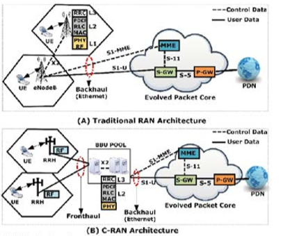
Figure 1: Architectural difference between traditional RAN and C-RAN. (A) traditional RAN architecture, (B) CRAN architecture.
Due to the full centralized structure of C-RAN, there is a vast communication overhead between RRH and BBU. Being only RF section at RRH, I/Q samples are sent over the fronthaul to the BBU for further processing. The required fronthaul data rate is directly proportional to the number of antennas used at RRH, due to which the use of C-RAN in 5G with massive MIMO seems to be hypothetical [9]. There are two possible directions to address the above problem, which are fronthaul compression and baseband functional split. In fronthaul compression, the I/Q data are compressed by using a suitable compression technique, as discussed in [10]. Under functional split, a redistribution of baseband functions among RRH and BBU are considered [11]. Due to the lightweight, it is easy to deploy a large number of RRHs in the given coverage area to increase the network capacity [5]. The two hop links, UE to RRH and RRH to BBU, increase propagation delay, which makes C-RAN technology not a suitable candidate for 5G in terms of latency requirements. These technical challenges, such as the design of fronthaul compression, different C-RAN, fronthaul architectures, and technical challenges of fronthaul, are discussed in this literature.
Under the Hardware design section, as part of the progress made in the hardware design for C-RAN, different test beds are studied to evaluate the merits and demerits involved in different functional split options.
There were already some existing works [5], [7], [11], [12], which discuss various technological advancements made in C-RAN. An introductory to C-RAN is given in [5], which explains a high-level overview of C-RAN architecture, network virtualization, and transport network. In [7], fronthaul design aspects, as well as the compression techniques, are discussed in detail. The field trials and testbed development for C-RAN are also highlighted. But the state-of-the-art technologies discussed in this work are not exhaustive and up to date. A comprehensive survey on various technologies, architecture, challenges, requirements, and proper potential solutions to achieve an efficient C-RAN fronthaul is studied in [12]. Schemes that can help in reducing system complexity, bandwidth requirement, cost, and latency are considered as part of this work. To reduce the overhead of the fronthaul, different functional splits proposed from both academia and industry are highlighted in [11]. The investigation of this work is about, how the choice of functional split affects the fronthaul network, both in terms of latency and bitrates. The comprehensive literature [11], [12] is dedicated to a focused area of C-RAN architecture. None of the research, except [7], are discussing the fronthaul design aspects of C-RAN, which is the primary concentration area of our work.
The rest of the paper is organized as follows. section 2 presents a literature survey on C-RAN systems architecture. The advantages of C-RAN are listed in section 3. section 4 describes the different types of fronthaul solutions with their pros and cons. The technical challenges faced by the present fronthaul types are presented in section 5. In section 6, various I/Q sample compression techniques are studied under Fronthaul compression. All compression schemes, such as distributed uplink compression, multivariate downlink compression, and point-to-point compression, are thoroughly discussed. The existing literature available on different C-RAN testbeds is presented in section 7. Our testbed, which is based on the Labview framework, is also shown in the same section. Finally, in section 8, the summary of the whole literature is provided.
From the inception phase of C-RAN, there has been a tremendous change in architecture, and this is evolving continuously. At the same time, a significant part of work is dedicated to the evaluation of architecture. To combat the current situation with data proliferation, the initial architecture is not fit for now, and it may so happen, existing architecture will not be fit for the near future. Thus, detailed and thorough surveying of this topic will help us to know the need for the continuous architectural change and future scope as well.
Though C-RAN architecture evaluation is the most dynamic field and changes a lot from the initial time, significant changes have been happening since 2015. But to make this survey more comprehensive, we will discuss some earlier work as well.
Handover is always a concern for cellular networks. In [13], the handover performance gain of C-RAN over traditional RAN for GSM, UMTS is discussed. Due to the synchronous nature of handovers in C-RAN, the performance gain is tenfold than that of decentralized RAN (D-RAN). Because of intrapool softer handover in C-RAN, the transport bandwidth requirement is also reduced. As the BBU pool is centralized and many RRHs are connected to the same BBU, handover management is much easier than a decentralized one.
Whether it is centralized RAN or distributed RAN, load balancing and massive data processing have always been a research topic. In the case of the traditional BS scenario, the processing element in each BS is designed to handle the peak load. So, the general processing unit does not work in this case. Most of the time, those resources are idle. But thanks to cloud computing, its related resource management, and the virtualization technique, any time resource can be added or removed. In [14], load analysis of C-RAN has been done. Apart from that analysis, a GPP based C-RAN architecture also proposed for the improvement of scalability, computation cost, consumption of power, unnecessary data movement, and inter-server communication. This work also maximizes CPU strength and flexibility. But for strengthening CPU power, some task scheduling algorithm is also viable, but that was not discussed. The mechanism of inter-server and intra-server communication is also not mentioned.
In [15], a novel end-to-end transport network solution is proposed. In this work, an innovative, WDM-PON based solution is discussed, where the availability of dedicated fiber is limited. A converged metro access network architecture has been proposed to support both centralized and distributed radio baseband solution. But this is mainly a backhaul related solution.
Now, as the baseband modules are mostly on the cloud and that too can be managed, a new business model comes into the picture. Along with infrastructure, platform, and software as a service model, a new concept called RAN as a service is a budding business model. In [16], using cloud computing and C-RAN, RAN as a service model is proposed. In this model, the challenges and their possible overcome strategies are discussed. RANaaS is a flexible model based on centralized processing and also capable of handling interference in a very dense network. In [17], architecture is also proposed to offer RAN as a service. The novel work in this paper proposed a simulation-based model to analyze the performance of the RANaaS model. But whether the architecture is feasible in terms of efficient resource allocation, computational complexity, and load balancing in a real scenario and on a large scale is yet to be decided as no emulation has been done yet.
Apart from the above-discussed problems, one big problem is the functional split. Functional split decides which processing block (e.g., source encoding, modulation/demodulation, multiplexing/demultiplexing, etc.) is to be placed at the RRH side and which is to be placed at BBU pool. If most of the processing blocks are placed in RRH, then data transmission to the BBU will be less. Thus, the bandwidth requirement will be reduced, but then the RRH design will be very complicated, leads to an increase in the total cost of ownership (TCO). If all the processing blocks are at the BBU pool, then raw samples have to be transmitted to the BBU; thus, the fronthaul bandwidth requirement will be much higher. So, there is always a trade-off between RRH complexity and fronthaul capacity in C-RAN. In [18], constraints and outline applications of flexible RAN centralization is analyzed. In this work, the performance by PHY layer functional split and MAC layer functional split is examined. In the case of the PHY layer functional split spatial diversity can be fully exploited. By implementing advanced processing, inter-cell interference can also be mitigated, or sometimes it increases the overall capacity. But in this case, high capacity, and low latency backhaul is required. In the case of the MAC layer split, it enables coordinated RRM and scheduling. But then RRH will be complex and costly, as well. At the same time, joint decoding, CoMP, etc. will not work in this case. But the technical challenge of doing this type of splitting is not discussed in their work.
Further, in [19], a practical implementation of C-RAN architecture in the context of 5G systems, with functional split taking into consideration, is discussed. In this work, the benefits and challenges of C-RAN for 5G architecture is analyzed. How different hardware options impact the implementation of C-RAN is thoroughly investigated. Backward compatibility with 3GPP LTE is another concern of C-RAN. In [19], the compatibility with 3GPP in terms of latency and throughput is shown. The flexibility of the proposed architecture is described from a practical point of view.
As the fronthaul capacity constraint is one of the bottlenecks, a graph-based approach is proposed in [20] to deal with limited fronthaul capacity. In this model, nodes of the graph are the baseband functions, links are the information flows, and the weight of the links is computational and front hauling cost. Finally, the optimum location is found out to place the baseband functions by finding the optimum clustering scheme for graph nodes. The problem is solved using a genetic algorithm with a customized fitness function and mutation module.
Cloud computing is the core concept of C-RAN. Due to its centrality, fronthaul complexity increases with the number of active users and data transmission. So, to overcome these problems, a new edge computing scheme like fog computing is proposed. In [21], harmonization of C-RAN and fog computing is established. Though both have some advantages and limitations, their harmonization can make the whole system very efficient. Here the concept of local link, i.e., device-to-device link in close proximity and the remote link, is used at the time of downloading any content. The load in cloud and device for the highest performance is analyzed in terms of latency, throughput, and error.
A unified model is proposed in [22]. Currently, various C-RAN models are proposed to explore the potential advantages of C-RANs. So a unified model of C-RAN for 5G is not straight forward.
Apart from RANaaS, C-RAN technology opens up many application fields where centralized processing of signal communication has to be done. As the resources are centralized and information from many different RRHs are coming to the baseband pool for processing, much joint processing for overall performance gain can be done efficiently. One of the recent works on this technology is the Indoor Distributed Antenna System (IDAS). In [23], an SDR based solution approach to tackle latency, fronthaul capacity resource control is discussed. At the same time, a practical implementation of the Indoor Distributed Antenna System (IDAS) is also presented by using the C-RAN platform. Their experimental study also discloses some answers like controlling the communication between RRH and BBU, managing BS resources in the server platform, impact of interface algorithm on the system. Traditional cloud computing resource sharing platform will not work in this case because of stringent timing constraints. How to use some advanced technology to deal with these timing constraints is still a research topic.
In 2016 a colossal work was done on the architecture of C-RAN. In [24], a novel model has been created to deal with high capacity data transfer in urban areas. In urban areas, there is a huge gap in data transfer rates between the business area and the residential area. In this work, a set of positions of BS is taken as input and come up with optimal BBU positions as output. To build the model, delay, load balance, and capacity requirement are considered as parameters. This analytical model is composed of four components, namely, RRH proliferation, BBU positioning, load balancing, and BBU dimensioning. The simulation results are promising and successfully evaluate the best deployment configuration from the operators’ perspective. The result also shows that in that way, the resources in the BBU pool can be decreased by up to 25% in their peak loads.
At the same time, in [25], critical technologies used in C-RAN are discussed. In this work, it was shown that traditional hexagonal topology does not fit with the current C-RAN deployment model. As the introduction of the microcell, picocell, femtocell in a multitier and ultra-dense network, HetNet topology cannot be depicted as a hexagonal grid because BS or RRHs are random in this case. Moreover, the ON/OFF facility in femtocell makes it more randomized. So, a frameless model is necessary. This model is called as Frameless Network Architecture (FNA). The stochastic geometry method, with a Poisson Point Process (PPP) model, has been proposed for this type of dynamic network. One very recent model, Ginibre Point Process (GPP), has been submitted for depicting this deployment topology. In FNA, there is no need for handover. The serving set will be updated automatically to ensure the QoS requirement.
In [26], a novel idea for the betterment of the performance of 5G HetNets and facilitate offloading management is presented. Their main aim is to create cloud RRH. That is another level of abstraction over the physical RRH. The physical RRHs are like femtocell, and many femtocells are connected to a small cell, that is the cloud RRH. The cloud RRH has CPU, memory, and storage space for intermediate processing. The physical RRH and the cloud RRH is connected by radio wireless link. The cloud RRHs are interconnected to each other through Z-interface. For resource and interference management, one RRH from each small cell will be connected to the BBU pool through CPRI Interface. In this way, CAPEX will be reduced. The result shows that Quality of Service (QoS) is enhanced compared to conventional C-RAN even though the authors have come up with some new approach of C-RAN architecture. Any efficient offloading algorithm is not mentioned. At the same time, how mobility and inter-cell interference can be handled in this type of scenario was also not discussed in this work.
In [27], an improved version of optical-access-enabled C-RAN architecture is proposed. To enhance signal qualities, CoMP and Train Relay Station plays a vital role in railway communication. For that, BS coordination is very much required. Now during the BS coordination, an excessive data exchange has to be done, thus occupying excessive bandwidth, and that will affect the backhaul transmission negatively. To get rid of that situation, Cross-BS fronthaul link (CFL) comes into the picture. In this case, even if two RRHs belong to different BSs trying to send data to a single BBU, one of them can use CFL to transmit the data directly to any one of the two BBUs. As a result of both traffic, i.e., the fronthaul and backhaul traffic can be sent simultaneously; hence, the High-Speed Railway (HSR) communication is improved.
Though tremendous advantages of C-RAN can be seen nowadays from data rate to the total cost of ownership, multicell coordination is one of the biggest hurdles. At the same time, as the fronthaul is not ideal, latency and performance of the system can be affected by the functional split as well. In [28], the authors have investigated the effect of coordination algorithms like coordinated scheduling, dynamic point selection, and uplink joint reception for a given fronthaul latency. It was shown that the coordination performance in fully centralized C-RAN is no better than fully distributed or partially distributed C-RAN. That means the architectural evolution towards decentralization is a correct way to combat the vast data processing jargon. Furthermore, pooling gain is also being examined in this work.
Due to Network Function Virtualization (NFV) and Softwarization in C-RAN, the performance is promising. But as this whole system is becoming very complicated, switching and aggregation concept in fronthaul must come into the picture. At the same time, to combat the limited fronthaul capacity constraints, the functional split is becoming indispensable. In [29], the problem of a functional split is analyzed, and a solution approached is also given. The main problems of functional split or flexible centralization are 1. RRHs become more complex, that means expensive 2. It reduces the opportunities for multiplexing gains, coordinated signal processing, and interference management. But at the same time, it reduces the fronthaul consumption in the order of magnitude. So, there is a trade-off between the complexity of RRH and fronthaul consumption. Now to transmit data through CPRI or OBSAI, packetization has to be done. Received samples from ME is first packetized in RRH, then that packets are sent to the BBU pool, de-packetization is done there to get the samples back. Finally, all baseband processing is done. Now the question is that at what point packetization should be done. The analysis shows that if packetization is done immediately after getting the samples, then FH consumption is very high. If packetization is done after CP removal and FFT conversion, then the consumption will be low. But in that case (de)-packetization latency will be higher. This work examined the most suitable packetization method, taking packetization latency and FH overload into consideration so that HARQ deadlines are met. But this is very situation-specific. The multiplexing gain for different UE densities and functional splits are analyzed, and a conclusion is drawn on the maximum number of supported RRHs for the best packetization method.
In [30], a flexible framework is proposed where the centralized BBU pool is connected to the SDN controller to make another level of intelligent abstraction for joint coordination and increase scalability. The novelty of the work is a definition of an architecture where given the practical constraints of real-time RAN, a Multiaccses coordination algorithm for joint processing is proposed, and this processing is centralized. It is also capable of end-to-end connectivity with enhanced QoS for cell-edge users; those are affected by ICI without CoMP.
In [31], new functional split architecture between RRHs and BBUs is investigated to reduce transmission throughput. Two novel architectures are proposed in this work. It was shown that in a fully loaded system, 30%-40% bandwidth could be saved, and if half of the radio channel is used, then up to 70% bandwidth can be saved using this new architecture. It is seen that when transmitting the LTE guard sub-carrier, CP makes a significant portion of redundant data. At the same time, some other redundant info is being sent, called Physical Resource Block (PRB), which is also sub-carrier. Generally, not all PRBs are occupied in LTE transmission. If this information can be inferred at the RRH, then only used PRB can be sent, thus less data to be sent. At the same time, if CP removal and FFT is done in RRH, then 50% of less data will be transmitted. Another way to reduce uplink data is first to change the signal from the frequency domain to the time domain. Then PRB usage state detection and finally the quantized data is sent to the BBU.
C-RAN has many advantages over traditional RAN, such as low CAPEX and OPEX, less cell interference, easy for maintenance, and fast deployment due to less civil work. Over the past years, C-RAN has been evolved, ranging from “centralized”, “cooperative” to “Cloud”. Being the final evolution, cloud RAN includes all the benefits from centralized and collaborative architecture. Due to the centralization of BBU at the BBU pool, on-demand resource allocation is possible, and resources are effectively utilized through resource sharing. BBU pool also helps in the mobility management of UEs. In the BBU pool, If any BBU is heavily loaded or fails, a backup BBU is always ready to connect through Software Defined Radio (SDR) switch. In traditional RAN, even though the CoMP scheme improves the cell edge throughput by reducing inter-cell interference, but the implementation of CoMP becomes a cumbersome task due to the extensive system overhead and the delay between the BSs [3]. Since in Cloud RAN, all the BBUs are located at a single location, maintaining the tight synchronization between the BBUs has become easy. In this way, as C-RAN structure is best suitable for the implementation of CoMP, and hence spectral efficiency can be improved [32].
A study on greenhouse emission in [33] says, 2% of the CO2CO2 global emission is contributed by information and communication technology (ICT) sector. By 2020, the carbon footprint is expected to be triple due to the massive growth of the cellular sector. Thus an energy-efficient system design is highly required to reduce CO2CO2 emission. C-RAN is an energy-efficient system as compare to traditional RAN. For a centralized BBU, the power consumption required for cooling the BBUs has come down due to a single room. Due to many to one mapping between RRH-BBU, a few BBUs are required in the BBU pool. It saves power consumption.
In C-RAN, RRH becomes very light, and the footprint is reduced due to the shifting of all layers and its functions to BBU. It becomes easy to install RRH, especially in dense urban and hilly areas. The requirement of less construction space for RRH installation helps in reducing CAPEX. In a short period, the installation of RRH is possible; hence network expansion can be easily done to increase the system capacity. To have an insight into the requirement of C-RAN and its benefit, we have chosen two typical areas, which are depicted in Figure. 2. The chosen areas are football stadium and airport, where better network coverage with high throughput is essentially required. By applying C-RAN architecture, an operator can get more benefits as compared to tradition RAN.
By implementing Network Function Virtualisation (NFV) over BBUs, it becomes possible to share the same resource among multiple operators. Thus, compared to traditional RAN, fewer resources are required in C-RAN. Hence, it helps in reducing the CAPEX. Cost efficiency is a main driver of NFV. Due to NFV, load-balancing, network scale up and down, move functions across distributed hardware resources become easy in C-RAN. It improves the flexibility of the network service provisioning and reduces the time to deploy new services.
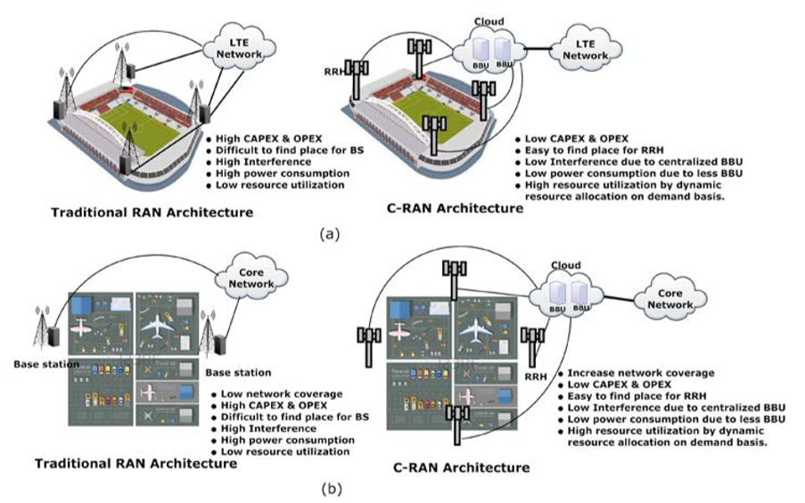
Figure 2: Benefits of C-RAN compare to traditional RAN. (a) Shows the football ground, (b) shows the airport area
In C-RAN, the interface that connects RRH and BBU is known as fronthaul. The concept of the fronthaul is not newly introduced in C-RAN. It was already present in traditional RAN architecture, but unnoticed. In traditional RAN, the fronthaul interface was used to allow the antenna function to be moved to the rooftops and mastheads, keep away from the baseband processing present inside the cabinet. It was unnoticed due to its short distance in the case of traditional RAN. But in C-RAN, the separation distance between the antenna head and BBU unit can be of several kilometers. The interface used for connecting RRH and BBU follows some dedicated transport standards, which is set by industry cooperation. The name of these standards are Open Base Station Architecture Initiative (OBSAI) [34], Common Public Radio Interface (CPRI) [35], Open Radio Interface (ORI) [36].
OBSAI was first introduced in 2002 by a common agreement among BS vendors: Hyundai, Nokia, LG Electronics, Samsung, and ZTE. The main aim of OBSAI was to open the market for creating cellular base station products by which the cost and development effort will be reduced. OBSAI-based fronthaul is a packet-based interface. It can achieve the data rate from 728 Mbps to 6.8 Gbps, and the BER requirement is 10-15. At the end of 2003, CPRI came to the picture as a result of cooperation among five radio equipment vendors: Ericsson, Huawei, NEC, Nortel Networks, and Siemens Mobile [37]. The interface that follows CPRI standard requires stringent performance requirements such as a maximum of 100μs100μs one-way latency, 65ns jitter, and 10-12 BER. CPRI supports a constant bit rate. It deals with layer 1 (physical layer) and layer 2 (MAC, RLC, and PDCP) protocol stack for defining a frame that carries I and Q samples. The mapping methods of CPRI are more efficient compared to OBSAI [38], and it is widely used by most of the global vendors.
CPRI has restricted compatibility as compared to OBSAI, due to its closed-based architecture. To address this problem and to provide better compatibility, the European Telecommunication Standards Institute (ETSI) has initiated a new industry specification group (ISG) known as ORI. ISG is also agreed by telecom operators like SK Telecom, Japanese telecommunications operator KDDI and vendors like Samsung, Huawei, ZTE. ORI specification is a modification on CPRI standards by the removal of some options and the addition of other functions. The main difference between CPRI and OBSAI on one side and ORI on other sides is that the first two technologies are formed by cooperation among equipment markers.
In contrast, ORI members include several network operators. All the three interfaces support digitized data. Among the three, CPRI is dominating and by-default, followed by the fronthaul interface. Sometimes the fronthaul interface is also called a CPRI interface.
In [39], an overview of CPRI and its application in the LTE scenario is well explained. A CPRI can support many topology such as star, tree, chain, ring, and multi-hop option. It can support different radio standards such as 3GPP UTRA FDD, 3GPP GSM/EDGE, and WiMAX apart from 3GPP EUTRA (LTE), which is our point of concern. CPRI requires strict synchronization and time accuracy between RRH and BBU. It supports an operating range of at least 10 km and a maximum of 40 km. Apart from the BW requirement, CPRI needs a stringent delay, jitter, and BER requirement. It allows the maximum of 200μs200μs delay for round trip transmission. The CPRI link can contribute maximum 5μs5μs delay, excluding the propagation delay. The maximum allowed frequency deviation from the link to the base station is of 0.002 ppm.
CPRI supports digital data, and it follows either Time Division Multiplexing (TDD) or Frequency Division Multiplexing (FDD). TDD is widely used in CPRI, and it has a hierarchical frame structure, as shown in Figure. 3. An LTE frame structure, also known as the CPRI frame, starts from a Basic Frame (BF) of variable size. BF allows transmitting user plane data, control, management plane data, synchronization, and timing data in each frame. It consists of 16 words from which 15 words carry user plane data and the starting word (W0W0 ) of a frame carry control, management, and synchronization data. Each word length of a BF depends on the number of bits required per I and Q sample and the number of antenna-carrier (A××C). A××C depends on the MIMO scheme and the number of antenna sectoring used. Basic frame duration (TcTc ) is just the reciprocal of the sampling frequency. In every TcTc , it is bound that a BF is created and transmitted. For the different channel, BW, and number of A××C, the required CPRI data rate is different. The line coding used in CPRI also depends on the number of A××C. A Collection of BFs equal to the number of FFT points is known as Hyper Frame. The duration of a Hyper frame is the summation OFDM symbol duration (66.67μs66.67μs) and the duration of Cyclic Prefix (CP). A Hyper frame contains 256 control words, one from each BF. These control words are organized into 64 sub-channels; each carries four control words. Total sub-channels divided into seven categories, and each sub-channel belongs to one category. A Grouping of 150 numbers of Hyper frame completes a 10ms of LTE frame (CPRI frame). All the existing fronthaul candidates follow the CPRI frame structure and its three mapping methods to accommodate different AxC
Existing Fronthaul candidates– A C-RAN system follows a full centralized structure for its smooth operation and maintenance. Due to this structure, RRH contains only the Radio Frequency (RF) section and has no processing power. So RRH collects the RF signal and sends sampled I/Q data (digital) to BBU for further processing. After processing, BBU sends the digitized data to RRH through the CPRI-based fronthaul link.
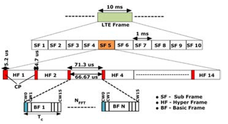
Figure 3: Hierarchical frame structure of CPRI for normal cyclic prefix [40].
There is a vast communication overhead between RRH and BBU due to the full centralized structure. For the above reason, the CPRI link demands a high fronthaul data rate. Fronthaul link with CPRI standard also follows other performance requirements such as maximum one-way delay, maximum jitter, and the allowable BER. These performance specifications are imposed by CPRI [41]. We can choose those fronthaul candidates who can satisfy the above CPRI requirements. List of existing fronthaul candidates are A) Optical fronthaul, B) Wireless fronthaul, and C) Ethernet fronthaul. From the above list of candidates, Ethernet fronthaul is a novel and emerging, fronthaul candidate. Optical fronthaul is widely used as compared to Ethernet and Wireless fronthaul.
Table 1: Different types of Optical fronthaul deployment technology with their pros and cons [43]
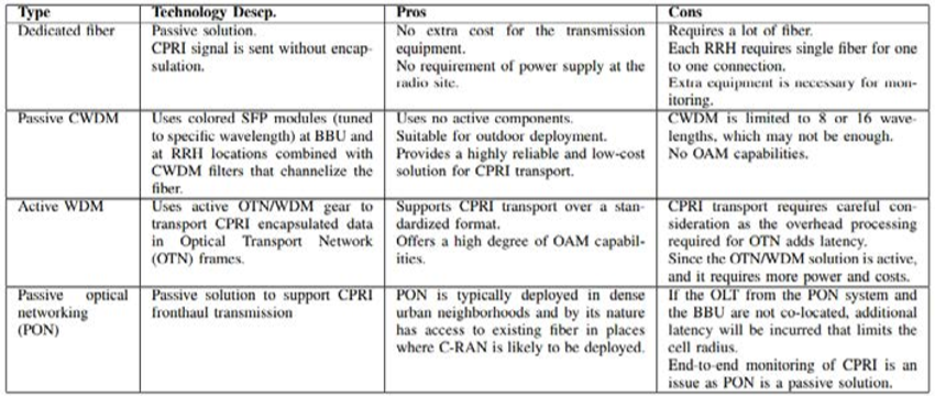
Early deployment of C-RAN in China, Japan, South Korea use optical fiber as the only fronthaul candidate. It is mainly due to its high BW and low latency. According to Mavrakis [42], optical fronthaul deployment can follow different technologies such as dedicated fiber technology, Passive CWDM technology, Active WDM technology, and Passive Optical Networking (PON) technology. All the above technology uses a mix of passive and active optical equipment. The advantages and disadvantages of each technique are listed in Table 1.
Wireless fronthaul seems to be an alternate of optical fronthaul. It is cheap. RRH can be installed anywhere due to no physical wire connection, lightweight, less space requirement, and less construction required. So, it is easy to install either in dense urban areas or any hilly region. It takes less time for setup. Due to its many advantages now, many vendors like EBlink, Cablefree are mainly focused on the development of wireless fronthaul. According to one of the vendor Cablefree [42], wireless latency is less compared to optical fiber due to the following reasons: 1) Optical fiber paths are not in a straight line, 2) Wireless propagation is faster (around 40%) than optical fiber due to lower refractive index of air than fiber.
The use of Ethernet for fronthaul is a recent development in C-RAN. For the successful implementation of Ethernet fronthaul, many projects such as CERN’s white rabbit project [44], European Union’s Horizon 2020 project (iCIRRUS) [45] are going on. Research groups like IEEE have already formed its task force named as IEEE1904.3 [46], IEEE1588 [47] and IEEE Standard Association (SA)1914 [48] for encapsulation of CPRI over Ethernet, its synchronization and for standardization. Ethernet fronthaul has the following benefits. Ethernet makes virtualization of C-RAN cheaper and easier as SDN is already developed for IP networks. Due to the use of routers/switches, statistical multiplexing gain is possible. Monitoring, fault finding, managing is possible due to Operation, Administration and Maintenance (OAM) operation over Ethernet. It is cost-effective and can use the existing Ethernet network.
In this section, the technical challenges of existing fronthaul candidates in terms of throughput, latency, and jitter requirement, their deployment issues, availability, and the future scope are mainly highlighted.
Optical fronthaul follows a physical wired connection. So for dense urban areas or hilly areas, it is not suitable for deployment of the optical fiber due to its inflexibility. It is also very unsuitable for disaster-prone regions. Implementation of optical fronthaul is a time-consuming process. One major disadvantage of optical fronthaul is its high cost. So for small distance areas, optical fronthaul is unsuitable. It is fully unsuitable for some regions like Africa, Southeast Asia, and some European countries which will not prefer to bear fiber deployment cost.
CPRI fronthaul capacity requirements are very high. It is difficult for a wireless link to achieve the growing demands of CPRI due to its constraints in terms of spectrum and distance if mm-wave is taken into account. Although vendors like EBlink have already proposed devices for wireless fronthaul, which can support up to 7.5Gbps CPRI data rate for 70MHz channel BW. While using the millimeter band, the wireless fronthaul can support up to 2.5Gbps for 500MHz channel BW [43]. In 5G, due to the use of a massive MIMO antenna system, the CPRI data rate requirement will be more than 100Gbps. It seems to be difficult for wireless fronthaul to support such a huge data rate.
For the existence of Ethernet fronthaul, it must meet the two major stringent performance requirements of CPRI, i.e., a) delay should be within 100μs100μs b) jitter should be within 65 ns. But standard Ethernet is unable to meet the performance limit. In standard Ethernet, although the delay is under control, jitter is very high (400 ns in the worst case) [49]. To carry time-sensitive traffic in Ethernet, IEEE has proposed two new enhancement technique named as IEEE802.1 Qbu (used frame preemption) and IEEE802.1 Qbv (used scheduling). In IEEE802.1 Qbu frame with lower priority is preempted by frame with higher priority, and a frame can be preempted several times.
Similarly, in 802.1 Qbv, a frame gets scheduled to a transmission gate, which is either an open or closed state. Timing signals control transmission gates. The experimental result says Ethernet with frame preemption can never achieve jitter requirement (65 ns) either with background traffic (packet injected by nodes) or only with CPRI traffic [50]. By using IEEE802.1 Qbv (Packet scheduling), it is possible altogether to remove jitter in case of without background traffic (only CPRI traffic). In the case of background traffic, jitter is below than CPRI standard. Jitter depends on the packet size and the slot size. By selecting a global scheduling instead of local scheduling, jitter can be removed entirely for the slot size of 1.5 times of Packet Transmission Time (PTT). Maximum delay achieved in the case of Ethernet with preemption for without background traffic is below to the CPRI standards, but it can’t reach jitter limit. In the case of Ethernet with scheduled traffic, the maximum delay is lower than 100μs100μs. So it is concluded that only IEEE802.1 Qbv is sufficient to make Ethernet fronthaul feasible for CPRI standards. The physical deployment of Ethernet fronthaul is still far away. All the above results and conclusions are simulation-based. It can not guarantee that Ethernet fronthaul can work in 5G.
The above three CPRI-based fronthaul is working well for 4G and the traditional network like 2G, 3G, but it is unsuitable for the next-generation network, like 5G. It is due to the following reasons.
A CPRI-based fronthaul carries I/Q sample data between BBU and RRH. This sampling data have a direct relationship with the number of antennas used at the RRH side. So the required fronthaul capacity, which is also known as the CPRI data rate, increases as the number of antenna increases. For example, A 2××2 and 4××4 antenna configuration with two sectors for 20MHz BW, the required CPRI rate is 4.9Gbps and 9.83Gbps respectively [39]. The fronthaul data rate is directly proportional to the number of sectoring and the number of antennas used in one sector. For each sector, the data rate gets double. For 5G, due to the use of 64 or even 128 antennas at RRH, the required data rate will become the bottleneck.
CPRI follows a constant data rate due to synchronous digital hierarchy-based (SDH-based) transmission mode [35]. So there is a chance of low utilization efficiency during the night time or maybe at non-official hours. Even for a dense urban area tidal wave effect is not noticeable at every time.
Under CPRI based connection, there is a fixed one to one correspondence between RRH and BBU pool. So during an emergency, one RRH cannot be automatically switched to another BBU pool by automatic routing. This kind of flexibility is missing.
Statistical multiplexing is absent in CPRI based communication. It is due to the distribution of time-domain radio waveform samples over a fronthaul network.
Missing of Operation, Administration, and Maintenance (OAM) operation.
The fronthaul links carry quantized IQ samples from RRH to BBU pool in uplink; and from BBU pool to RRH in the downlink. The fronthaul links are supposed to meet the upcoming 5G standards in terms of low latency and high data rates. The enormous data rates produced by the quantized IQ samples exploit fronthaul capacity limitation, which is the main bottleneck in the commercial deployment of C-RAN. This fronthaul capacity limitation will degrade the Large Scale Collaborative Processing (LSCP) gain that could be achieved through C-RAN architecture. Ex:- With densely deployed RRHs and with a UE operating around a few MHz bandwidths will increase the data rate of fronthaul link that connects the particular RRH to BBU pool will scale up to several Gbps. Hence, uplink and downlink fronthaul compression are required. There are two possible ways to achieve fronthaul compression. One of them is partial C-RAN architecture. In this architecture, RRHs are given some responsibility to do some signal processing that could be done at the BBU-pool, but this will oppose the whole idea of easy network densification to achieve network capacity. Hence the design of robust fronthaul compression techniques is needed that can support the full-centralization of C-RAN architecture.
There are several fronthaul compression techniques available to reduce the fronthaul IQ data rate, which can be used depending on the requirement. The point-to-point compression technique can be used in low complexity scenarios. point-to-point compression techniques are generally the basic IQ sample quantization methods. But point-to-point compression alone cannot serve the purpose in many cases. point-to-point compression can be used along with network-aware compression techniques like distributed source coding and joint compression. These network-aware compression techniques bring complexity to the analysis. Spatial filtering and Compressive Sensing (CS) based compression are other types of compression techniques. Like a point-to-point compression technique, spatial filtering is also a low complexity technique. The original idea behind the CS-based compression is to exploit the signal sparsity among UEs. Hence CS-based compression and spatial filtering cannot be used for the downlink signal compression. As part of CS-based compression and spatial filtering, the received UE’s signal will be multiplied with the local RRH matrix. This will lead to a reduction in the dimension of the received signal. Similarly, distributed source coding can only be used for the uplink compression. The basic idea of distributed source coding is to exploit the correlation among the received signals at RRH. Another network-aware compression technique, joint compression, can be used at the BBU side for downlink compression.
In the following subsections, the uplink compression and downlink compression are discussed. Mostly, the compression techniques discussed under the uplink and downlink compression subsections are not simple point-to-point compression techniques. The quantization-based and similar point-to-point compression techniques are discussed separately under point-to-point compression subsection.
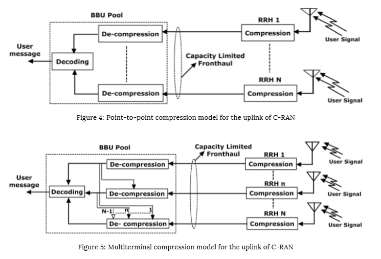
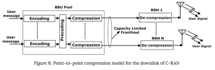
The uplink compression techniques are mainly two types, point-to-point compression, and multiterminal compression. The point-to-point compression at the uplink side is shown in Figure. 4, where the received signals at each RRH are compressed and transmitted to the BBU pool on a capacity limited fronthaul. At the BBU pool side, the compressed signals from each RRH are decompressed separately, but all these decompressed signals are decoded jointly. This is based on the assumption that the BBU does joint decoding based on all quantization values from all RRHs. But, in multiterminal compression, as shown in Figure. 5, the decompressor takes the correlation among the received RRH signals into account, and decompress accordingly.
Since the signals received at different RRHs are correlated, the distributed source coding based fronthaul compression can be considered as an alternative to reduce the fronthaul data rate by removing the redundant information. However, to implement this technique, each RRH requires information about the joint statistics of the received signals across other RRHs. As part of this compression technique, at each step, an RRH compresses its received signal based on the statistical information of the compressed signal of active RRHs at the previous step. These RRHs are generally sensitive to uncertainties regarding such as correlation of the received signal’s information. The imperfect knowledge of the joint statistics of the signals received at RRHs can lead to performance degradation of distributed source coding. Distributed source coding is based on the idea of reducing the rate of the compressed stream by incorporating some uncertainty in the compressed stream. This uncertainty is resolved with the help of side information. The amount of rate reduction that is allowed without decompression errors is dictated by the quality of side information, which should be known at the cloud decoder. Hence, the lack of side information at the cloud decoder may result in decompression error of received signal at RRH.
By taking these correlation errors into account, a robust distributed uplink compression scheme at multi-antenna RRHs is proposed in [51], where distributed compression is implemented with the help of sequential source coding and side information. The knowledge of joint statistics at each RRH is represented in a covariance matrix, which is considered to be imperfect. The uncertainty is modeled using a deterministic additive error model with bounds on the eigenvalues of the covariance matrix. Bounding these eigenvalues is equivalent to bounding any norm of the error. The problem is formulated as a worst-case deterministic approach problem. The stationary solution to this problem is achieved by solving KKT conditions. The simulation results suggest that, even with sizable errors, the proposed compression scheme gave the benefits of the distributed compression scheme. Whereas, the errors in the statistical model of the side information makes the distributed source coding useless.
Moreover, the network energy efficiency problem is addressed by selecting active RRHs. A joint optimization problem of compression and RRH selection is formulated by introducing sparsity inducing terms in the objective function. To solve this problem, an iterative block-coordinate ascent algorithm is proposed, which is converged to a locally optimal point. The quantization noise introduced while doing the compression operation, which is the critical parameter of fronthaul compression. The quantization noise level is optimized based on a per-RRH base.
The performance evaluation of standard point-to-point and multiterminal fronthaul compression techniques for both uplink and downlink of C-RAN are studied in [52]. The simulation results are carried over standard cellular networks by focusing on performance metrics such as proportional-fairness utility, sum-rate, and cell-edge throughput. The multiterminal fronthaul compression showed 60% performance gain more compared to that of standard point-to-point fronthaul compression. Hence, it is claimed that the point-to-point fronthaul compression techniques fail to achieve optimal performance in even the simplest multiterminal settings of C-RAN.
The work proposed in [53] deals with the optimization of fronthaul compression. Here uplink C-RAN model is considered, where the fronthaul link is noiseless and has finite sum capacity constraint. The independent messages sent from each UE within a cooperating cluster, interfere with other UE’s messages at their respective RRH. The RRHs compress and forward these received UE messages, which are decoded successively at the centralized processor. The quantization codewords are decoded initially. Later, based on the quantized signals from all the RRHs, the UE’s messages are decoded. This compression, decompression, and decoding operations are done within the constant gap to the sum capacity of the network. In this way, the uplink C-RAN model can be thought of as a Virtual Multiple Access Channel (VMAC) between UEs and BBU pools while RRHs acting as relays. Distributed Wyner-Ziv (WZ) coding, and Single-User (SU) compression are considered as the candidates for compression at RRH. These compression techniques are named by the authors as VMC-WZ and VMAC-SU, respectively. The main objective of this work is to set the optimization levels for quantization noise. The quantization noise level of all RRHs is optimized jointly. The optimization of quantization noise levels for VMAC-ZV is formulated as a weighted sum-rate maximization under fronthaul capacity constraints, which is solved through alternating convex optimization algorithm. For VMAC-SU, the problem is reformulated in terms of optimizing fronthaul capacities. It was observed that, during the high Signal-to-Quantization-Noise-Ratio (SQNR) times, setting the quantization noise levels proportional to background noise levels, irrespective of channel conditions and transmission power is near-optimal to attain maximum sum rate. With that choice of quantization noise level, VMAC-ZV schemes achieve the sum capacity of the uplink C-RAN model within the constant gap. VMAC-SU produces a similar constant gap with diagonally dominant channel conditions. Since VMAC schemes have low decoding complexity and low decoding delay as compared to joint decoding, these consistent gap results motivate to extend this VMAC scheme in practical C-RAN.
The benefits of exploiting the uplink signal sparsity are not utilized in [52], [53], and hence the uplink signal sparsity structure is ignored in those works. Because of the uplink delay-sensitive services or the random access of the UEs in the uplink transmission, the transmission is bursty, which leads to the sparsity of the uplink packets. This uplink sparsity can be used to reduce the fronthaul loading. Classical distributed CS technique can’t be used directly for C-RAN. In traditional Classical distributed CS, signals are compressed distributively at different sensors, and later the joint recovery of these signals is made. Like conventional distributed CS technique, the uplink signals are compressed locally at RRHs. Still, these signals are an aggregation of multi-users transmitted from different UEs over multiaccess fading channels. Hence in C-RAN, the target of joint recovery at the BBU pool is the transmitted signals from UEs rather than the locally received signals from RRHs. So, if a distributed CS algorithm is used for joint signal recovery in C-RAN, it should incorporate multiaccess fading effects of C-RAN in it. For Robust CS recovery, restricted isometry property (RIP) is commonly adopted to derive sufficient conditions; but establishing adequate conditions for the RIP of the associated measurement matrix is non-trivial. Conventional results about the RIP condition can’t be applied for the aggregate CS measurement matrix, because of the complicated multiaccess fading channels between UE and RRHs in C-RAN system. Hence, by embracing multiaccess fading, a new characterization of the sufficient conditions for robust CS recovery should be done. While applying CS signal recovery to achieve fronthaul compression, it is also important to quantify a closed-form trade-off between uplink C-RAN capacity and the fronthaul loading at each RRH. All these challenges are addressed in [54] by proposing an uplink C-RAN model and distributed fronthaul compression at each RRH. A joint signal recovery is made at the BBU pool by using distributed CS, which exploits multiaccess fading between the UEs and RRHs and the signal sparsity of UEs. The aggregated CS measurement matrix contains both the multiaccess fading and distributed fronthaul compression. The performance of the end-to-end signal recovery algorithm is analyzed, and it was showed that the aggregated CS measurement matrix satisfies the RIP conditions with high probability under some mild conditions. Based on these results, the correct probability of active user detection is analyzed. Furthermore, the achievable uplink capacity is characterized in terms of the fronthaul compression rate, which will help conclude uplink performance and fronthaul loading.
CS is an effective method for signal acquisition and processing. The key idea of this technique is that the collected signals are not purely random, and hence can be compressed because of the redundancy. So, this nature can be taken as prior knowledge for compression and recompression of the collected signals. Therefore, CS provides a new sampling paradigm for sparse signals and enables the decoder to retrieve the original signal accurately from the reduced number of samples. The CS-based distributed fronthaul compression in [54] considers the uplink random access channel scenario between UEs and RRHs. Still, in general, only the active UEs and the uplink signals are sparse. Thus, by considering the correlation of the received uplink baseband signals at different RRHs within one cluster, a compressive sensing based uplink compression is proposed in [55]. To save the transport expenses in a multi-clustered C-RAN, one cluster Head (CH) collects the information from all the RRHs and sends it to the BBU pool. Since the number of RRHs are huge in a C-RAN cluster, the amount of information collected at CH would be too high to transmit over a capacity limited fronthaul. Whereas, the collected information at different RRHs within one cluster is correlated in nature because of the multiaccess fading effect. So, the CH performs CS-based fronthaul compression before transmission, and the BBU implements the joint recovery to reconstruct the gathered uplink signals by RRHs. Later, the original baseband signals of all the UEs are decoded at the end using a Successive Interference Cancellation (SIC) mechanism. The uplink rate increases with the UE SNR and the SIC implemented at the BBU side. It was also observed that the SNR increases with the fronthaul capacity, and the maximum SNR can be reached when the measurement channel capacity equals the fronthaul capacity.
All the works till now studied the fronthaul compression schemes, in which the RRH communicates to the BBU pool by itself. The fronthaul compression scheme for multihop C-RAN is considered in [56], where each RRH manages to communicate with BBU through a set of intermediate RRHs. In this work, the generalized C-RAN model is followed, where each RRH either compresses and forwards or forwards the received baseband signal without any demodulation. Initially, a baseline Multiplex-and-Forward (MF) scheme is studied, in which each RRH receives the bitstream from a connected RRH and forwards it without any processing. It was observed that the MF scheme leads to performance degradation in the case when each RRH has many incoming links from other RRHs. To overcome this problem, the Decompress-Process-and-Recompress (DPR) scheme is proposed. In the DPR scheme, RRH decompresses the received bitstream and performs the linear in-network processing of the decompressed signals. Both MF and DPR fronthaul schemes are designed to maximize the sum-rate under the limited fronthaul capacity constraints. The advantage of in-network processing is highlighted by comparing the performance of MF and DPR strategies. The optimal solutions in the DPR scheme demand full CSI, but acquiring full CSI at every RRH is difficult in the case of dense C-RAN. Hence a decentralized DPR scheme for the optimal solution is proposed, where the RRHs require only local CSI to compute linear processing. The future extension of this work is the consideration of non-linear in-network processing at the RRHs, investigating the ways to utilize the side information available at intermediate RRHs, and the consideration of imperfect CSI of other RRHs at every RRH.
Multiple antenna RRHs are considered while study-ing the uplink C-RAN compression technique in [57]. In order to exploit this multi-antenna spatial sparsity, a Spatial-Compression-and-Forward (SCF) technique is proposed. Rather than using a complex quantization scheme like the authors did in [51], [53], a less complex linear filter is considered for compressing the received correlated signals at all the antennas of each RRH. An optimization problem is framed to maximize the minimum SNR of all the users. The optimization problem considers the joint optimization of the user’s power allocation, RRH’s spatial filter design and quantization bits allocation, and BBU’s receive beamforming.
A localization problem of positioning a single antenna radio transmitter in the C-RAN system is studied in [58]. The problem is formulated as the quantization strategy optimization while minimizing the worst case localization error under fronthaul capacity constraints. The Charnes-Cooper transformation and difference-of-convex programming are utilized to design corresponding optimization algorithms. From the numerical simulations, it was observed that the localization becomes better with the large fronthaul capacity. It was also shown that the fronthaul rate requirements are less for localization when compared to data communication.
Industry and Academia propose different C-RAN architectures. Out of them, Fully centralized and Partially centralized C-RAN architectures are popular ones. In Fully centralized C-RAN architecture, RRH is associated with only the RF section, and BBU has L1/L2/L3 layers. This architecture helps to increase the network capacity by increasing the density of the RRHs, whereas huge fronthaul capacity is required to transfer the IQ samples. In Partially C-RAN architecture, along with the RF section, RRH is also associated with L1 layer functionality. Hence, less capacity fronthaul link connection is sufficient between RRH and BBU pool; but the network expansion is not so easy due to the increase in complexity of the RRH. Hence, a decision needs to be made on the final architecture of C-RAN through various experiments on a hardware test-bed. There is much software available to support the cloud RAN setup; out of them, OAI (Open Air Interface) is the popular one. OAI is initially developed by EURECOM and made as open-source by OpenAir Interface Software Alliance. OAI is the real-time software written in the C-programming language and can be supported on the Linux platform. 3-GPP protocol stack for Evolved Universal Terrestrial Radio Access (E-UTRAN) and EPC is wholly implemented in OAI.
In [74], Next Generation Fronthaul Interface (NGFI) based C-RAN architecture is emulated with the help of OAI frame-work, commodity hardware, and Ethernet fronthauling. Since, CPRI-based C-RANs are not able to meet the scalability and performance requirements, NGFI redefines the fronthaul transport network architecture through baseband splitting between BBU and RRH. In NGFI terminology, BBU is termed as Radio Cloud Center (RCC) and RRH as Remote Radio Unit (RRU). The performance of the Time-domain I/Q split (IF5) and frequency-domain I/Q split (IF4) are analyzed in this work. In IF4 split, some of the physical layer processing such as FFT/IFFTs and IQ sample compression. After employing a low compression at the RRH side, it is observed that almost 28% of the capacity requirement has come down as compared to IF5 split. The same work is explained in detail by the same group of authors in [75]. Both the functional splits are compared in terms of different performance metrics like fronthaul throughput, the round trip delay between fronthaul and RF circuits, the CPU utilization, data plane delay, and data plane QoS.
Similar kinds of work with OAI software supported Ethernet fronthaul based C-RAN testbed is studied in [76] by MAC layer split at RCC. RRU is kept with RF and Physical layer processing functionalities. Unlike CPRI, Ethernet fronthaul can’t be used for transportation of high data rate IQ sample data. MAC layer split at the RCC relieves the burden of high data requirements over Ethernet fronthaul by sending MAC PDUs to the Physical layer at the RRU. Latency, jitter, and throughput for different sizes of packet data are studied in this work. As part of latency, the round trip delay is calculated between RRC’s MAC layer and RRU’s Physical layer to avoid synchronization issues. The packet data consists of overhead in the form of Ethernet header, and MAC-PHY control header. The overhead is considered in throughput calculation.
PDCP is used in IP based networks. PDCP does packet compression and removes the IP header before processing the packet further down to the lower layers. RLC transfers higher layer PDUs to MAC SDUs. MAC layer does resource allocation to the UEs, and the scheduled transmissions are delivered to the PHY layer in subframes. In the PDCP/RLC split, the PDCP layer is kept in BBU and RLC, and it’s below layers are present at RRU. After the RLC process, the received packet from PDCP will be kept in buffer till the MAC protocol sends a request for it. A right amount of buffer needs to be maintained at the RRU so that it won’t run out of memory. In MAC/PHY split, the MAC layer is kept in the BBU and PHY layer along with RF present in RRU. The PDCP/RLC split is not much advantageous, since many transmissions are required to the BBU as the RLC layer didn’t do concatenation at the BBU. MAC/PHY split has its advantages, such as beamforming coordination and dynamic scheduling of multiple UEs. Given these points, PDCP/RLC and MAC/PHY split performance in downlink is studied in [77] using real-time heterogeneous testbed and OAI emulation platform. The communication between BBU and RRU is carried over 1 Gbps copper link, and it is termed as a backhaul link. The throughput achieved in both cases is studied under different Modulation and Coding Scheme (MCS) and Transport Block Size (TBS). PDCP/RLC is analyzed using a stateless protocol, UDP, and stateful protocols TCP and STCP. UDP achieves more throughput than the other stateful protocols, TCP and STCP. As STCP implementation for Linux kernel is not good enough, TCP outperforms STCP. MAC/PHY layer split is studied using the UDP protocol, and a throughput of 14 Mbps is achieved.
While coming to other technologies, IQ sample compression is the important one to alleviate fronthaul capacity requirement. In [78], partial bit sampling compression is proposed to compress IQ samples. The proposed scheme is compared along with already existing compression techniques like Non-linear quantization and block scaling. These comparisons are carried by implementing these compression techniques using the Xilinx Zynq 706 evaluation board and Xilinx FPGA. All three compression techniques are compared using up/down sampling. In the proposed partial bit sampling scheme, up/down sampling achieves 25% compression. Later the IQ sample is converted to 15 bits. As part of the algorithm, the low-order five bits are removed to compress the data. While recovering, those bits are replaced with 1'and1′and0′ assuming Gaussian distribution. This process achieves around 50% CPRI data compression. To validate the proposed scheme, EVM, compression delay, and FPGA logic utilization are observed. EVM degradation for partial bit sampling is found to be less than 0.2%. The delay caused by the introduction of the compression logic is called compression delay, which is found to be 3.2μ3.2μsec and 4.8μ4.8μsec, respectively, for partial bit sampling/non-linear quantization and block scaling. The extra delay of 1.6μ1.6μsec for block scaling is because of the complex logic involved in it. The FPGA logic utilization is compared among all three compression techniques along with up/down sampling. Non-linear quantization utilizes 100%, whereas Partial bit sampling utilizes 85.7%, and block scaling utilizes 86.2%.
In [79], C-RAN controller architecture is designed and experimentally tested to reconfigure the network if the network performance is in degradation. As BBUs are located in the Central Office (CO), a CO controller is present to monitor received power and BER for optical transponders and latency, jitter, and BER for CPRI protocol. CPRI has some firm requirements like the one-way delay of 100μ100μ sec, maximum jitter of 65 nsec, and BER of 10-12. When the detected data from packet nodes and BBU shows degradation, a notification will be sent from the CO controller to the C-RAN controller. Upon receiving the request, the C-RAN controller releases the used resources and allot the new ones. This proposed model is experimentally validated using SYNERGY test-bed.
In [80], the processing time of LTE subframes, and delay performance are measured for OAI based C-RAN setup. It was observed that the LTE subframes processing time increases with the number of PRBs and MCS index.
None of the above mentioned works have compared the performance of C-RAN with the traditional RAN. We have analyzed the performance difference in the following section.
We have emulated the C-RAN setup with the Labview framework and NI USRP 2943R [81]. As the implementation of the LTE framework on the Labview framework is a tedious job. Thus, we have experimented with a packet transceiver scenario to mimic the C-RAN setup. Ethernet fronthaul was used as a communication link between RRH and BBU. UDP and TCP protocols were used for the fronthaul transmission. To understand the intricacies of fronthaul limitation, a comparison between C-RAN and traditional RAN is observed for performance metrics like goodput, and total latency. Since, it was a point-to-point link, not much drop in the goodput of C-RAN was observed with TCP protocol. But, the fronthaul latency in C-RAN was observed to be very high as compared to traditional RAN.
The latency and drop in fronthaul data increase with the increase in the number of RRHs. Hence, the necessity of fronthaul compression is observed. We are working towards a better IQ sample quantization technique, which can balance the trade-off between the compression ratio and EVM.
Even though C-RAN architecture was proposed a few years ago, the fronthaul limitation acting as a hurdle for the practical deployment. Many solutions like change in C-RAN architecture, fronthaul compression, edge caching, etc., are proposed to alleviate the burden on the fronthaul link, but they aid up to only some extent. The change in C-RAN architecture brings a limitation on the densification of network to achieve high network capacity and introduces complexity at the RRH, which nullifies the purpose of the introduction of Fully centralized C-RAN. Various fronthaul compression techniques that were also studied not supporting the 5G data rate requirements. Network-information theoretic compression techniques are performing better as compared to point-to-point compression techniques based on quantization. Hence, there is a need for the design of more robust network-information theoretic compression techniques to make C-RAN a feasible network architecture.
[1] Cisco Corporation, “Cisco visual networking index: Global mobile data traffic forecast, 2016-2021,” 2016.
[2] N. Bhushan, J. Li, D. Malladi, R. Gilmore, D. Brenner, A. Damnjanovic, R. Sukhavasi, C. Patel, and S. Geirhofer, “Network densification: the dominant theme for wireless evolution into 5g,” IEEE Communications Magazine, vol. 52, no. 2, pp. 82–89, 2014.
[3] J. Wu, Z. Zhang, Y. Hong, and Y. Wen, “Cloud radio access network (c-ran): a primer,” IEEE Network, vol. 29, no. 1, pp. 35–41, 2015.
[4] C. Mobile, “C-ran: the road towards green ran,” White Paper, ver, vol. 2, 2011.
[5] A. Checko, H. L. Christiansen, Y. Yan, L. Scolari, G. Kardaras, M. S. Berger, and L. Dittmann, “Cloud ran for mobile networksâÄŤa tech-nology overview,” IEEE Communications surveys & tutorials, vol. 17, no. 1, pp. 405–426, 2015.
[6] T. Salman, “Cloud ran: Basics, advances and challenges,” Wireless and Mobile Networking, 2016.
[7] M. Peng, Y. Sun, X. Li, Z. Mao, and C. Wang, “Recent advances in cloud radio access networks: System architectures, key techniques, and open issues,” IEEE Communications Surveys & Tutorials, vol. 18, no. 3, pp. 2282–2308, 2016.
[8] I. Chih-Lin, J. Huang, R. Duan, C. Cui, J. X. Jiang, and L. Li, “Recent progress on c-ran centralization and cloudification,” IEEE Access, vol. 2, pp. 1030–1039, 2014.
[9] I. Chih-Lin, Y. Yuan, J. Huang, S. Ma, C. Cui, and R. Duan, “Rethink fronthaul for soft ran,” IEEE Communications Magazine, vol. 53, no. 9, pp. 82–88, 2015.
[10] S.-H. Park, O. Simeone, O. Sahin, and S. S. Shitz, “Fronthaul compression for cloud radio access networks: Signal processing advances inspired by network information theory,” IEEE Signal Processing Magazine, vol. 31, no. 6, pp. 69–79, 2014.
[11] L. M. Larsen, A. Checko, and H. L. Christiansen, “A survey of the functional splits proposed for 5g mobile crosshaul networks,” IEEE Communications Surveys & Tutorials, 2018.
[12] I. A. Alimi, A. L. Teixeira, and P. P. Monteiro, “Toward an efficient c-ran optical fronthaul for the future networks: A tutorial on technologies, requirements, challenges, and solutions,” IEEE Communications Surveys & Tutorials, vol. 20, no. 1, pp. 708–769, 2017.
[13] L. Liu, F. Yang, R. Wang, Z. Shi, A. Stidwell, and D. Gu, “Analysis of handover performance improvement in cloud-ran architecture,” in Communications and Networking in China (CHINACOM), 2012 7th International ICST Conference on. IEEE, 2012, pp. 850–855.
[14] L. Guangjie, Z. Senjie, Y. Xuebin, L. Fanglan, N. Tin-fook, Z. Sunny, and K. Chen, “Architecture of gpp based, scalable, large-scale c-ran bbu pool,” in Globecom Workshops (GC Wkshps), 2012 IEEE. IEEE, 2012, pp. 267–272.
[15] Z. Ghebretensaé, K. Laraqui, S. Dahlfort, F. Ponzini, L. Giorgi, S. Stracca, J. Chen, Y. Li, J. Hansryd, and A. R. Pratt, “Transmission solutions and architectures for heterogeneous networks built as c-rans,” in Communications and Networking in China (CHINACOM), 2012 7th International ICST Conference on. IEEE, 2012, pp. 748–752.
[16] D. Sabella, P. Rost, Y. Sheng, E. Pateromichelakis, U. Salim, P. Guitton-Ouhamou, M. Di Girolamo, and G. Giuliani, “Ran as a service: Challenges of designing a flexible ran architecture in a cloud-based heterogeneous mobile network,” in Future Network and Mobile Summit (FutureNetworkSummit), 2013. IEEE, 2013, pp. 1–8.
[17] L. S. Ferreira, D. Pichon, A. Hatefi, A. Gomes, D. Dimitrova, T. Braun, G. Karagiannis, M. Karimzadeh, M. Branco, and L. M. Correia, “An architecture to offer cloud-based radio access network as a service,” in Networks and Communications (EuCNC), 2014 European Conference on. IEEE, 2014, pp. 1–5.
[18] A. Maeder, M. Lalam, A. De Domenico, E. Pateromichelakis, D. Wubben, J. Bartelt, R. Fritzsche, and P. Rost, “Towards a flexible functional split for cloud-ran networks,” in Networks and Communications (EuCNC), 2014 European Conference on. IEEE, 2014, pp. 1–5.
[19] D. Sabella, P. Rost, A. Banchs, V. Savin, M. Consonni, M. Di Girolamo, M. Lalam, A. Maeder, and I. Berberana, “Benefits and challenges of cloud technologies for 5g architecture,” in Vehicular Technology Conference (VTC Spring), 2015 IEEE 81st. IEEE, 2015, pp. 1–5.
[20] J. Liu, S. Zhou, J. Gong, Z. Niu, and S. Xu, “Graph-based framework for flexible baseband function splitting and placement in c-ran,” in Communications (ICC), 2015 IEEE International Conference on. IEEE, 2015, pp. 1958-1963.
[21] S.-C. Hung, H. Hsu, S.-Y. Lien, and K.-C. Chen, “Architecture harmonization between cloud radio access networks and fog networks,” IEEE Access, vol. 3, pp. 3019-3034, 2015.
[22] M. Peng, Y. Li, Z. Zhao, and C. Wang, “System architecture and key technologies for 5g heterogeneous cloud radio access networks,” IEEE network, vol. 29, no. 2, pp. 6–14, 2015.
[23] Y. D. Beyene, R. Jäntti, and K. Ruttik, “Cloud-ran architecture for indoor das,” IEEE Access, vol. 2, pp. 1205–1212, 2014.
[24] A. Marotta and L. M. Correia, “A model to evaluate c-ran architectures deployment impact in urban scenarios,” in Broadband Communications for Next Generation Networks and Multimedia Applications (CoBCom), International Conference on. IEEE, 2016, pp. 1–6.
[25] X. Xu, Z. Sun, X. Dai, X. Tao, and P. Zhang, “A frameless network architecture for the way forward of c-ran,” China Communications, vol. 13, no. 6, pp. 154–166, 2016.
[26] O. Chabbouh, S. B. Rejeb, Z. Choukair, and N. Agoulmine, “A novel cloud ran architecture for 5g hetnets and qos evaluation,” in Networks, Computers and Communications (ISNCC), 2016 International Sympo-sium on. IEEE, 2016, pp. 1–6.
[27] H. Liu, N. Hua, Y. Li, Y. Li, and X. Zheng, “A solution for high-speed railway communication enabled by an improved c-ran architecture,” in Optical Fiber Communications Conference and Exhibition (OFC), 2016. IEEE, 2016, pp. 1–3.
[28] R. Agrawal, A. Bedekar, S. Kalyanasundaram, T. Kolding, H. Kroener, and V. Ram, “Architecture principles for cloud ran,” in Vehicular Technology Conference (VTC Spring), 2016 IEEE 83rd. IEEE, 2016, pp. 1–5
[29] C. Chia-Yu, S. Ruggero, N. Navid, S. Thrasyvoulos, and B. Christian, “Impact of packetization and functional split on c-ran fronthaul performance,” in Proc. of IEEE ICC, 2016.
[30] D. Boviz, N. Abbas, G. Aravinthan, C. S. Chen, and M. A. Dridi, “Multi-cell coordination in cloud ran: Architecture and optimization,” in Wireless Networks and Mobile Communications (WINCOM), 2016 International Conference on. IEEE, 2016, pp. 271–277.
[31] J. Duan, X. Lagrange, and F. Guilloud, “Performance analysis of several functional splits in c-ran,” in Vehicular Technology Conference (VTC Spring), 2016 IEEE 83rd. IEEE, 2016, pp. 1–5.
[32] P. Rost, C. J. Bernardos, A. De Domenico, M. Di Girolamo, M. Lalam, A. Maeder, D. Sabella, and D. Wübben, “Cloud technologies for flexible 5g radio access networks,” IEEE Communications Magazine, vol. 52, no. 5, pp. 68–76, 2014.
[33] J. Malmodin, Å. Moberg, D. Lundén, G. Finnveden, and N. Lövehagen, “Greenhouse gas emissions and operational electricity use in the ict and entertainment & media sectors,” Journal of Industrial Ecology, vol. 14, no. 5, pp. 770–790, 2010.
[34] O. B. S. A. Initiative et al., “Bts system reference document, version 2.0,”
http://www.obsai.com/specs/OBSAI_System_Spec_V2.0.pdf, 2006.
[35] C. P. R. Interface, “Interface specification v6. 0,” Acedido em, vol. 28, 2013.
[36] O. R. equipment Interface, “Requirements for open radio equipment interface (ori)(release 4), etsi std., oct. 2014.”
[37] A. Pizzinat, P. Chanclou, F. Saliou, and T. Diallo, “Things you should know about fronthaul,” Journal of Lightwave Technology, vol. 33, no. 5, pp. 1077–1083, 2015.
[38] M. Nahas, A. Saadani, J.-P. Charles, and Z. El-Bazzal, “Base stations evolution: Toward 4g technology,” in Telecommunications (ICT), 2012 19th International Conference on. IEEE, 2012, pp. 1–6.
[39] A. de la Oliva, J. A. Hernández, D. Larrabeiti, and A. Azcorra, “An overview of the cpri specification and its application to c-ran-based lte scenarios,” IEEE Communications Magazine, vol. 54, no. 2, pp. 152-159, 2016.
[40] M. Rumney et al., LTE and the evolution to 4G wireless: Design and measurement challenges. John Wiley &Sons, 2013.
[41] A. Ericsson et al., “Common public radio interface (cpri); interface specification v7. 0,” Huawei Technologies Co. Ltd, NEC Corporation, Alcatel Lucent, and Nokia Networks, 2015.
[42] http://www.cablefree.net/wirelesstechnology/4glte/cpri-front-haul-technology/.
[43] D. Mavrakis, “Why fronthaul matters–a key foundation for centralized and cloud rans,” White Paper. Ovum, 2015.
[45] C. Pan, Y. Kai, H. Zhu et al., “intelligent converged network consolidat-ing radio and optical access around user equipment,” Resource, vol. 27, p. 07, 2017.
[46] I. . A. N. W. Group et al., “Some views on next generation radio interface,” 2015.
[47] I. S. Association et al., “Standard for a precision clock synchronization protocol for networked measurement and control systems,” IEEE 1588, 2002.
[48] I. . W. Group et al., “Next generation fronthaul interface.”
[49] T. Wan and P. Ashwood, “A performance study of cpri over ethernet,” 1904.
[50] T. Wan and P. Ashwood-Smith, “A performance study of cpri over ethernet with ieee 802.1 qbu and 802.1 qbv enhancements,” in Global Communications Conference (GLOBECOM), 2015 IEEE. IEEE, 2015, pp. 1–6.
[51] S.-H. Park, O. Simeone, O. Sahin, and S. Shamai, “Robust and efficient distributed compression for cloud radio access networks,” IEEE Transactions on Vehicular Technology, vol. 62, no. 2, pp. 692–703, 2013.
[52] â, “Robust layered transmission and compression for distributed uplink reception in cloud radio access networks,” IEEE Transactions on Vehicular Technology, vol. 63, no. 1, pp. 204–216, 2014.
[53] Y. Zhou and W. Yu, “Optimized backhaul compression for uplink cloud radio access network,” IEEE Journal on Selected Areas in Communications, vol. 32, no. 6, pp. 1295–1307, 2014.
[54] X. Rao and V. K. Lau, “Distributed fronthaul compression and joint signal recovery in cloud-ran,” IEEE Transactions on Signal Processing, vol. 63, no. 4, pp. 1056–1065, 2015.
[55] Y. Wang, Z. Chen, and M. Shen, “Compressive sensing for uplink cloud radio access network with limited backhaul capacity,” in Computer Science and Network Technology (ICCSNT), 2015 4th International Conference on, vol. 1. IEEE, 2015, pp. 898–902.
[56] S.-H. Park, O. Simeone, O. Sahin, and S. Shamai, “Multihop backhaul compression for the uplink of cloud radio access networks,” IEEE Transactions on Vehicular Technology, vol. 65, no. 5, pp. 3185–3199, 2016.
[57] L. Liu and R. Zhang, “Optimized uplink transmission in multi-antenna c-ran with spatial compression and forward,” IEEE Transactions on Signal Processing, vol. 63, no. 19, pp. 5083–5095, 2015.
[58] S. Jeong, O. Simeone, A. Haimovich, and J. Kang, “Optimal fronthaul quantization for cloud radio positioning,” IEEE Transactions on Vehicular Technology, vol. 65, no. 4, pp. 2763–2768, 2016.
[59] S.-H. Park, O. Simeone, O. Sahin, and S. Shamai, “Joint precoding and multivariate backhaul compression for the downlink of cloud radio access networks,” IEEE Transactions on Signal Processing, vol. 61, no. 22, pp. 5646–5658, 2013.
[60] â, “Inter-cluster design of precoding and fronthaul compression for cloud radio access networks,” IEEE Wireless Communications Letters, vol. 3, no. 4, pp. 369–372, 2014.
[61] P. Patil and W. Yu, “Hybrid compression and message-sharing strategy for the downlink cloud radio-access network,” in Information Theory and Applications Workshop (ITA), 2014. IEEE, 2014, pp. 1–6.
[62] J. Kang, O. Simeone, J. Kang, and S. Shamai, “Fronthaul compression and precoding design for c-rans over ergodic fading channels,” IEEE Transactions on Vehicular Technology, vol. 65, no. 7, pp. 5022–5032, 2016.
[63] B. Guo, W. Cao, A. Tao, and D. Samardzija, “Cpri compression transport for lte and lte-a signal in c-ran,” in Communications and Networking in China (CHINACOM), 2012 7th International ICST Conference on. IEEE, 2012, pp. 843–849
[64] S. Nanba and A. Agata, “A new iq data compression scheme for front-haul link in centralized ran,” in Personal, Indoor and Mobile Radio Communications (PIMRC Workshops), 2013 IEEE 24th International Symposium on. IEEE, 2013, pp. 210–214.
[65] J. Lorca and L. Cucala, “Lossless compression technique for the fronthaul of lte/lte-advanced cloud-ran architectures,” in World of Wire-less, Mobile and Multimedia Networks (WoWMoM), 2013 IEEE 14th International Symposium and Workshops on a. IEEE, 2013, pp. 1–9.
[66] K. F. Nieman and B. L. Evans, “Time-domain compression of complex-baseband lte signals for cloud radio access networks,” in Global Conference on Signal and Information Processing (GlobalSIP), 2013 IEEE. IEEE, 2013, pp. 1198–1201.
[67] D. Samardzija, J. Pastalan, M. MacDonald, S. Walker, and R. Valenzuela, “Compressed transport of baseband signals in radio access networks,” IEEE Transactions on Wireless Communications, vol. 11, no. 9, pp. 3216–3225, 2012.
[68] Z. He, C. Hu, T. Peng, and C. Ma, “A compression scheme for lte baseband signal in c-ran,” in Communications and Networking in China (CHINACOM), 2014 9th International Conference on. IEEE, 2014, pp. 202–207.
[69] B. Guo, W. Cao, A. Tao, and D. Samardzija, “Lte/lte-a signal compres-sion on the cpri interface,” Bell Labs Technical Journal, vol. 18, no. 2, pp. 117–133, 2013.
[70] D. Peng-ren and Z. Can, “Compressed transport of baseband signals in cloud radio access networks,” in Communications and Networking in China (CHINACOM), 2014 9th International Conference on. IEEE, 2014, pp. 484–489.
[71] L. Ramalho, M. N. Fonseca, A. Klautau, C. Lu, M. Berg, E. Trojer, and S. Höst, “An lpc-based fronthaul compression scheme,” IEEE Communications Letters, vol. 21, no. 2, pp. 318–321, 2017.
[72] H. Si, B. L. Ng, M. S. Rahman, and J. Zhang, “A novel and efficient vector quantization based cpri compression algorithm,” IEEE Transactions on Vehicular Technology, vol. 66, no. 8, pp. 7061–7071, 2017.
[73] L. Ramalho, I. Freire, C. Lu, M. Berg, and A. Klautau, “Improved lpc-based fronthaul compression with high rate adaptation resolution,” IEEE Communications Letters, vol. 22, no. 3, pp. 458–461, 2018.
[74] S. S. Kumar, R. Knopp, N. Nikaein, D. Mishra, B. R. Tamma, A. A. Franklin, K. Kuchi, and R. Gupta, “Flexcran: Cloud radio access network prototype using openairinterface,” in Communication Systems and Networks (COMSNETS), 2017 9th International Conference on. IEEE, 2017, pp. 421–422.
[75] C.-Y. Chang, N. Nikaein, R. Knopp, T. Spyropoulos, and S. S. Kumar, “Flexcran: A flexible functional split framework over ethernet fronthaul in cloud-ran,” in Communications (ICC), 2017 IEEE International Conference on. IEEE, 2017, pp. 1–7.
[76] G. Mountaser, M. L. Rosas, T. Mahmoodi, and M. Dohler, “On the fea-sibility of mac and phy split in cloud ran,” in Wireless Communications and Networking Conference (WCNC), 2017 IEEE. IEEE, 2017, pp. 1–6.
[77] N. Makris, P. Basaras, T. Korakis, N. Nikaein, and L. Tassiulas, “Experimental evaluation of functional splits for 5g cloud-rans,” in Communications (ICC), 2017 IEEE International Conference on. IEEE, 2017, pp. 1–6.
[78] S. H. Kim, H. S. Chung, and S. M. Kim, “Experimental demonstration of cpri data compression based on partial bit sampling for mobile front-haul link in c-ran,” in Optical Fiber Communication conference. Optical Society of America, 2016, pp. W1H–5.
[79] L. Gifre, M. Ruiz, A. Castro, R. Proietti, S.-J. B. Yoo, and L. Velasco, “Experimental assessment of degradation-triggered reconfiguration in optically interconnected cloud-ran,” in Optical Fiber Communications Conference and Exhibition (OFC), 2017. IEEE, 2017, pp. 1–3.
[80] T. X. Tran, A. Younis, and D. Pompili, “Understanding the computational requirements of virtualized baseband units using a programmable cloud radio access network testbed,” in Autonomic Computing (ICAC), 2017 IEEE International Conference on. IEEE, 2017, pp. 221–226.
[81] V. B. Vinnakota, N. Manne, A. Mondal, D. Sen, and S. Chakraborty, “An experimental study of c-ran fronthaul workload characteristics: Protocol choice and impact on network performance,” in 2019 IEEE 89th Vehicular Technology Conference (VTC2019-Spring). IEEE, 2019, pp. 1–7.