
In this series of articles on Experiential Learning of Networking Technologies, we have discussed a number of network protocols starting from HTTP [7] at application layer, TCP [3] and UDP [1] protocols at transport layers that provide end to end communications, and IP addressing [2] and routing for packet delivery at network layer. We have defined a number of experiential exercises for each underlying concept which provide a practical understanding of these protocols. Now, we would like to take a holistic view of these protocols which we have learned so far and look at how all these protocols come into play when an internet user makes a simple web request, e.g., what happens from network perspective when a user enters google.com in the URL bar of a web browser [12]. From the perspective of user, web page of Google’s search interface is displayed in the browser window, but inside the network both at the user’s local network and the internet, a lot of network activity takes place. The focus of this article is to understand the traversal of packets in the network triggered by any such user activity.
The Figure 1 depicts a typical setup and internet connectivity where a user accesses the internet. For example, this could be office network, academic institute or even a home user. In a home network setup, a user today is typically connected using wireless (Wi-Fi) (or using a cellular data network). When a user is connected via Wi-Fi access point (or a cell tower), the latter acts as a layer 2 switch, which in turn is connected to a router which in turn connects to the internet. This is shown in Figure 2.
Figure 1: A typical network connectivity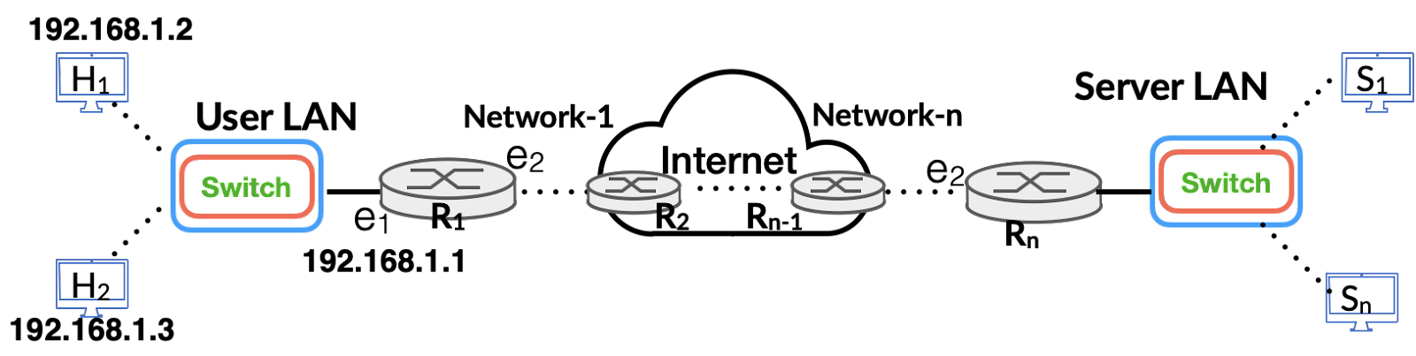
Figure 2: Network setup connectivity with WiFi
In general, the local network setup is connected to internet via an edge router, also referred to as broadband router or home router etc., which serves as the first hop and is connected using either fiber or DSL (Digital Subscriber Line – via a phone line) to the local ISP (Internet Service Provider). The ISP in turns carries user traffic to internet which consists of many network elements such as routers and switches, and at the other end, ISP network(s) is connected to server network, which is typically hosted in a cloud data center.
2 Getting Connected: DHCP and Ethernet
Any internet access requires that user’s device (PC, phone, laptop etc.) must be assigned an IP address so as to enable it to communicate with internet. When a user powers up the device, it generally gets the IP address using DHCP (Dynamic Host Configuration Protocol) [6]. This is generally the case for almost any user unless the device is configured statically to use fixed IP address and fixed DNS (Domain Name Server) address [5]. A brief description of typical exchange of DHCP protocol to obtain IP address, default gateway or router and DNS server is described in [8]. The working of DHCP protocol is shown in Figure 3.
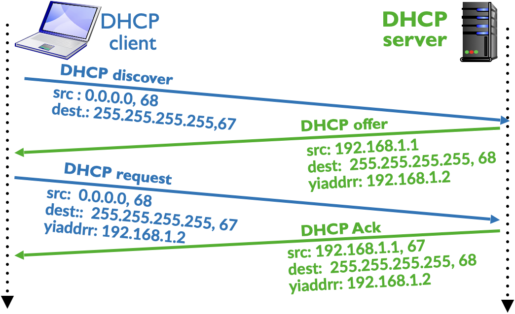
Figure 3: Use of DHCP to get IP Address
The first network activity from user’s perspective, even though it happens automatically on power up of a device, corresponds to sending a DHCP request to obtain an IP Address. This process typically results in exchange of 4 messages. In Figure 3, user’s device gets the IP address as 10.10.1.11 from the DHCP Server (with the IP address 10.10.1.1). Using the DHCP protocol, a user’s device also gets the IP address of default router and DNS server (for reasons of brevity, this information is not depicted in DHCP protocol communication shown in Figure 3). Humans are good at remembering and recollecting names rather than numbers, and thus any internet access, e.g., browsing, starts with the name of website or host as entered by the user. Computers communicate with each other using IP Address and we need a mechanism that maps the hostname to IP address. This role is performed by the DNS server. Thus, for all practical purposes, network configuration at user’s device also requires configuring the IP address of DNS server. For example, when user enters google.com in the browser, browser communicates with DNS server to get the IP address corresponding to gogole.com and only then it can send packets to Google. Thus, DHCP server generally provides the address of DNS server as part of DHCP handshake. Similarly, it also provides the IP address of default router, so that device can send packets to internet.
Generally, IP address assigned by a DHCP server has a validity period associated with it i.e., the IP address is assigned for a specific duration, called lease period, which typically in an office or home setup would be 12hrs to 24hrs, but in public places e.g., airport lounge, it is generally of shorter duration, such as 1hr to 2 hrs. After the expiry of lease period, device needs to renew the IP address which can be done by just exchange of DHCP Request and DHCP Ack message and first two messages DHCP Discover and DHCP Offer are not used during the renewal process. Whenever a user shuts down the laptop gracefully, the DHCP client sends a DHCP Release (not shown in Figure 3) message so that DHCP server can reuse the IP address if so required. However, generally, a user simply closes the laptop screen (rather than graceful shutdown) and thus DHCP Release is generally not observed in the network activities. At the expiry of the lease period, when DHCP server does not get renewal request, it puts back this IP address in the pool of available IP addresses which can be assigned later to other clients. Since the DHCP communication occurs one time at the start i.e., at power on time of device, for our understanding of packet traversal, we will consider that user has been assigned an IP address for long lease period and it is properly configured with a default router and a valid DNS server.
For our analysis of packet traversal and for holistic understanding of networking protocols, we will consider a simple network setup as shown in Figure 4. The core network, representing the internet, consists of 4 routers, and 1 DNS server (IP address 8.8.8.8 represents an open DNS server in internet) and a web server (IP address 10.10.6.1) hosting a website www.example.edu. The client machine which will access the internet has the IP Address 10.10.1.1 with its default router as R1 (IP address 10.10.1.11). For our discussion, it is assumed that all IP addresses are properly configured as shown in the Figure 4. Further, it is assumed that each router is configured with a default routing entry as follows. For router R1, R2, R3 and R4, default router is corresponding configured as 10.10.2.12; 10.10.3.11, 10.10.5.12 and 10.10.4.11 . The default router entry for system A, DNS server and web servers are respectively configured as 10.10.1.11, 8.8.8.1, and 10.10.6.11. A detailed discussion on understanding and usage of routing table entries to route packets is given in [9].
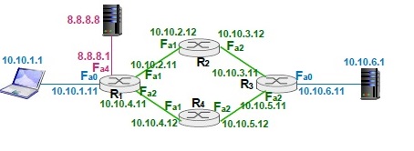
Figure 4: Network setup to trace the traversal of packets in Internet
3 First Network Activity: DNS and ARP
When a user on system A opens the browser and enters the URL http://www.example.edu, this results in a series of network events which leads to the web browser displaying the content of the web page as returned by the webserver. A common perception among network community is that when user enters the URL, system will immediately construct a HTTP request, and this HTTP request packet is the first packet that is transmitted by system A. In reality, transmission of this HTTP request packet occurs much later in the series of network events, which are triggered by the user action of entering the URL. Transmission of HTTP request requires setting up of TCP socket connection between system A and the web server, which implies that former first needs to get the IP address of web server. Thus, unless system A obtains the IP address of the web server www.example.edu, no communication can take place between the browser and the web server. To find the IP address corresponding to www.example.edu, system A needs to send DNS query to DNS server (IP address 8.8.8.8) and receive response that contains mapping of the hostname www.example.edu to its IP address 10.10.6.1. However, before this DNS query, which is carried inside a UDP packet, can be sent, another network activity needs to complete. This DNS query message triggers another network activity at system A which corresponds to obtaining the MAC (Media Access Control) address corresponding to IP address 10.10.1.11 using ARP (Address Resolution Protocol) [4]. Thus, a simple web request results in a series of network events one after the other before user actually sees the web page in the browser. The focus of this article is to look at each of these network events and understand traversal of associated packets in the network.
To obtain the IP address of hostname www.example.edu, system A constructs a DNS query message and puts the string www.example.edu in the question section of DNS [5]. The DNS message is carried over UDP protocol and thus a UDP segment is created with destination port of 53 (DNS server listens on UDP port 53 by default), This UDP segment is incorporated in an IP datagram with a destination IP address of 8.8.8.8 (IP address of DNS server) and with its source IP address as 10.10.1.1 (system A). Since DNS server is not on the local network of system A, this IP packets needs network routing and therefore it should be delivered to default router R1 with IP address 10.10.1.11.
The IP packet, containing the UDP segment having DNS query, needs to be encapsulated in an ethernet frame which needs to be sent at link layer (ethernet network or Wi-Fi network) to router R1. The delivery at ethernet layer requires that sender must know the MAC addrss of receiver i.e., interface Fa0 of router R1 having the IP address 10.10.1.11. Thus, the occurrence of first network activity corresponds to transmission of an ARP Query message, broadcasted by system A asking the network to provide it with the MAC address corresponding to IP address 10.10.1.11. Thus, first packet that is seen by the network is ARP query request as shown in entry #1 in Table 1. The Table 1 lists all the network packets with required relevant details that are transmitted in order of sequence corresponding to the web request initiated by the user to access the web page http://www.example.edu. Router R1 responds with ARP reply (a unicast message) to system A, providing its MAC address and is shown as entry #2. Readers can refer to [9] for a brief discussion and experiential learning of ARP protocol communication. Now that system A has got the MAC address of interface Fa0 or router R1, it is ready to send the DNS query message. System A now sends the DNS Query message, using UDP as transport layer, which makes use of IP and finally which is encapsulated in ethernet frame. Thus, network packet for this DNS query message will have source MAC address of system A, destination MAC address of Fa0 interface of R1, source IP address as 10.10.1.1 (system A), destination IP address as 8.8.8.8 (DNS Server), source port number X (which can be any available port between 1024 and 65545 on system), destination port as 53, and protocol being DNS/UDP. This is shown as entry #3 in Table 1.
4 Routing and Communication with DNS Server
When router R1 receives the ethernet frame and extracts IP datagram with the destination IP address as 8.8.8.8, it consults its routing tables to determine the link and next hop to forward this packet. As per Figure 4, DNS server is on local network connected to router R1 on ethernet interface Fa4. Thus, to deliver this packet to DNS server, router R1 needs to know the MAC address of DNS server and needs to use ARP protocol. Router R1 creates an ARP query message asking for MAC address corresponding to the IP address 8.8.8.8, encapsulates it in the ethernet frame with destination MAC Address as FF:FF:FF:FF:FF:FF (broadcast MAC address) and broadcasts this ARP query message on to the network connected with interface Fa4. This is shown as entry #4 in Table 1. DNS server receives the ARP query and responds with appropriate ARP reply. DNS server has already received the source MAC address of R1Fa4 interface in ARP query and thus has all the information to create Ethernet frame to encapsulate ARP Reply. The transmission of this packet is shows at entry #5 in Table 1. Now router has all the required information to construct an ethernet frame to transmit the waiting DNS query message. Thus, it transmits DNS query message transported over UDP carried over IP datagram and encapsulated in ethernet frame with source MAC of interface of R1Fa4 and destination MAC address of DNS server, source IP as 10.10.1.1 (system A) and destination IP with 8.8.8.8 (DNS Server), and is shown as entry #6. It should be noted that IP addresses in the IP datagram for this DNS query corresponds to system A (source) and DNS server (destination) and does not contain any of router’s IP address.
Table 1: Tracking traversal of network packets for TCP SYN segment
| SN | N/w Link | Src MAC | Dst MAC | Src IP: Port | Dstn IP: Port | Protocol |
| 1 | A – R1Fa0 | MAC of A | FF:FF:FF:FF:FF:FF | 10.10.1.1 | 255.255.255.255 | ARP query for IP 10.10.1.1. |
| 2 | R1Fa0 – A | MAC of R1Fa0 | MAC of A | 10.10.1.11 | 10.10.1.1 | ARP Reply for 10.10.1.1 |
| 3 | A – R1Fa0 | MAC of A | MAC of R1Fa0 | 10.10.1.1:X | 10.10.1.11:53 | DNS/UDP query for www.example.edu |
| 4 | R1Fa4 – DNS | MAC of R1Fa4 | FF:FF:FF:FF:FF:FF | 8.8.8.1 | 255.255.255.255 | ARP Query for IP 8.8.8.8 |
| 5 | DNS – R1Fa4 | MAC of DNS | MAC of R1Fa4 | 8.8.8.8 | 8.8.8.1 | ARP Reply for 8.8.8.8 |
| 6 | R1Fa4 – DNS | MAC of R1Fa4 | MAC of DNS | 10.10.1.1:X | 8.8.8.8:53 | DNS/UDP query for www.example.edu |
| 7 | DNS- R1Fa4 | MAC of DNS | MAC of R1Fa4 | 8.8.8.8:53 | 10.10.1.1:X | DNS reply for host www.example.edu |
| 8 | R1Fa0 – A | MAC of R1Fa0 | MAC of A | 8.8.8.8:53 | 10.10.1.1:X | DNS reply for host www.example.edu |
| 9 | A- R1Fa0 | MAC of A | MAC of R1Fa0 | 10.10.1.1:Y | 10.10.6.1:80 | TCP SYN pkt to web server |
| 10 | R1Fa1 – R2Fa1 | MAC of R1Fa1 | FF:FF:FF:FF:FF:FF | 10.10.2.11 | 255.255.255.255 | ARP Query for IP 10.10.2.12 |
| 11 | R2Fa1– R1Fa1 | MAC of R2Fa1 | MAC of R1Fa1 | 10.10.2.12 | 10.10.2.11 | ARP reply for IP 10.10.2.12 |
| 12 | R1Fa1– R2Fa1 | MAC of R1Fa1 | MAC of R2Fa1 | 10.10.1.1:Y | 10.10.6.1:80 | TCP SYN pkt to web server |
| 13 | R2Fa2 – R3Fa1 | MAC of R2Fa2 | FF:FF:FF:FF:FF:FF | 10.10.3.12 | 255.255.255.255 | ARP Query for IP 10.10.3.11 |
| 14 | R3Fa1-R2Fa2 | MAC of R3Fa1 | MAC of R2Fa2 | 10.10.3.11 | 10.10.3.12 | ARP reply for IP 10.10.3.11 |
| 15 | R2Fa2-R3Fa1 | MAC of R2Fa2 | MAC of R3Fa1 | 10.10.1.1:Y | 10.10.6.1:80 | TCP SYN pkt to web server |
| 16 | R3Fa0 – WS | MAC of R3Fa0 | FF:FF:FF:FF:FF:FF | 10.10.6.11 | 255.255.255.255 | ARP Query for IP 10.10.6.1 |
| 17 | WS – R3Fa0 | MAC of WS | MAC of R3Fa0 | 10.10.6.1 | 10.10.6.11 | ARP reply for IP 10.10.6.1 |
| 18 | R3Fa0 – WS | MAC of R3Fa0 | MAC of WS | 10.10.1.1:Y | 10.10.6.1:80 | TCP SYN pkt to web server |
DNS server receives the DNS query message on its UDP socket listening on port 53, extracts the hostname www.example.edu, searches into its database and retrieves the IP address 10.10.6.1 corresponding to this hostname. It then constructs a DNS reply message, and sends it using UDP socket with source port of 53 and destination port as X. The UDP segment which is encapsulated in IP datagram and is transmitted as payload to ethernet frame with source MAC of DNS server and destination MAC of interface R1Fa4. The DNS server already has the MAC address of R1Fa4 and thus has the required information to create and transmit the ethernet frame. The transmission of this message is shown at entry #7 in Table 1 indicating 7th network event. This DNS reply when received by router R1 results in following action. R1 extracts the IP datagram from the received ethernet frame, searches its routing table for destination address 10.10.1.1 in its routing table and determines that this packet is to be forwarded on interface Fa0 to System A. Router R1 already has the MAC address of A in its cache, which was stored when it first received ARP query from system A, and thus creates an ethernet frame, encapsulates the IP datagram received from DNS server corresponding to DNS reply and transmits to system A. This is shown in entry #8 in Table 1. This ethernet frame is delivered to system A which extracts the DNS reply to find the IP address 10.10.6.1 corresponding to hostname www.example.edu. It is now ready to actually send HTTP request message to web server.
5 Web Interaction: HTTP and TCP
HTTP protocol runs on top of TCP and thus system A first needs to setup a TCP connection with web server before it can transmit the HTTP request message for URL http://www.example.edu. System A invokes TCP socket connect() API with destination IP of 10.10.6.1 and destination port 80 (default port on which web server receives requests). The invocation of socket connect() API results in 3-way handshake for TCP connection setup [10], and system A sends TCP SYN message corresponding to next activity seen by the underlying network. This is shown as entry #9. The network stack on invocation of connect() API, associates a free TCP port Y (in the range 1024-65535) with its socket. As before, network packet for TCP SYN message will have source MAC of A, destination MAC of R1Fa0, source IP of A, destination IP of web server i.e. 10.10.6.1, source port Y, and destination port as 80. This packet is delivered to router R1. It should be noted that IP datagram contains the source and destination IP address as of sending host and receiver host and does not contain IP address of any intermediate routers. The source and destination IP addresses in the network packet remains the same throughout on all link transmissions. On link to link basis, only source MAC and destination MAC addresses are different as applicable for the link.
Router upon receiving TCP SYN segment encapsulated inside IP datagram which is further encapsulated in the ethernet frame, extracts the IP datagram, and consults its forwarding table to determine next hop to forward this IP packet with the destination IP address 10.10.6.1. As per default route entry, router R2 is default route for router R1, this IP datagram needs to be forwarded on its interface Fa1 to next hop (in the path to webserver) with the IP address 10.10.2.12. Since this is the first packet to R2 from router R1, it needs to use ARP protocol to find the MAC address corresponding to IP address 10.10.2.12. As discussed earlier, it constructs and broadcasts ARP query message with it source IP as 10.10.2.11 corresponding to interface R1Fa1, which is shown as entry #10 in Table 1. The corresponding ARP reply by router R2 is shown in entry #11. After receiving ARP reply for IP address 10.10.2.12, router R1 forwards the TCP SYN segment (waiting in its buffer )to router R2, and is shown in entry #12.
Router R2 undergoes same steps of network events to forward this packet to next hop R3. As per routing table, R3 corresponds to its default router, it needs to forwards this TCP SYN segment with destination IP of 10.10.6.1 to R3. It completes its routing activity by sending ARP query for IP address 10.10.3.11, receives the ARP reply from router R3 and then forwards the TCP SYN segment to R3. These 3 network packets transmissions are shown in entries #13, #14 and #15.
Web server 10.10.6.1 is connected on local network of router R3 and thus when R3 receives TCP SYN segment, it extracts the destination IP address 10.10.6.1 from the underlying IP datagram, consults its routing table, and determines that this packet needs to be delivered to a destination host on the local network connected via its ethernet interface R3Fa0. To deliver this packet to web server, it undergoes same sequence of transmitting ARP query for IP address 10.10.6.1, receiving ARP reply from web server and finally transmitting TCP SYN segment. The TCP SYN segment when forwarded by router R3 and received by web server would have source MAC address corresponding to R3Fa0, destination MAC address of Web Server, source IP as 10.10.1.1 of system A, destination IP 10.10.6.1 of web server, and TCP source port as Y and destination port as 80. Transmission of these 3 network packets is shown respectively in entries #16, #17 and #18 in Table 1.
Web server is the final destination of TCP SYN segment. After receiving the ethernet frame, it extracts IP datagram, determines that it is consumer of this datagram since the destination IP in the received datagram corresponds to its IP address, decapsulates IP datagram to extract TCP segment and passes it to TCP software stack. Since web server is listening on port 80 and waiting for a new connection request, TCP stack on web server accepts this connection and constructs TCP SYN-ACK segment in response to be sent to system A.
In the network of Figure 4, router R4 is the default next hop router for router R3 and similarly, router R1 is the default next hop router for router R4. Thus, the TCP segment containing TCP SYN-ACK segment corresponding to 2nd message of TCP 3-way handshake follows a different path than the path followed by TCP SYN message. In internet, it is quite likely that return path can be different than forward path and the routing configuration in network of Figure 4 depicts the same. The sequence of transmission of all network packets corresponding to TCP SYN-ACK is shown in Table 2.
Table 2: Tracking traversal of network packets for TCP SYN-ACK/ACK segments
| SN | N/w Link | Src MAC | Dst MAC | Src IP: Port | Dstn IP: Port | Protocol |
| 1 | WS – R3Fa0 | MAC of WS | MAC of R3Fa0 | 10.10.6.1:80 | 10.10.1.1:Y | TCP SYN-ACK |
| 2 | R3Fa2– R4Fa2 | MAC of R3Fa2 | FF:FF:FF:FF:FF:FF | 10.10.5.11 | 255.255.255.255 | ARP query for IP 10.10.5.12 |
| 3 | R4Fa2– R3Fa2 | MAC of R4Fa2 | MAC of R3Fa2 | 10.10.5.12 | 10.10.5.11 | ARP Reply for IP 10.10.5.12 |
| 4 | R3Fa2– R4Fa2 | MAC of R3Fa2 | MAC of R4Fa2 | 10.10.6.1:80 | 10.10.1.1:Y | TCP SYN-ACK |
| 5 | R4Fa1– R1Fa2 | MAC of R4Fa1 | FF:FF:FF:FF:FF:FF | 10.10.4.12 | 255.255.255.255 | ARP query for IP 10.10.4.11 |
| 6 | R1Fa2– R4Fa1 | MAC of R1Fa2 | MAC of R4Fa1 | 10.10.4.11 | 10.10.4.12 | ARP Reply for IP 10.10.4.11 |
| 7 | R4Fa1– R1Fa2 | MAC of R4Fa1 | MAC of R1Fa2 | 10.10.6.1:80 | 10.10.1.1:Y | TCP SYN-ACK |
| 8 | R1Fa0 – A | MAC of R1Fa0 | MAC of A | 10.10.6.1:80 | 10.10.1.1:Y | TCP SYN-ACK |
| 9 | A – R1Fa0 | MAC of A | MAC of R1Fa0 | 10.10.1.1:Y | 10.10.6.1:80 | TCP ACK to web server |
| 10 | R1Fa1 – R2Fa1 | MAC of R1Fa1 | MAC of R2Fa1 | 10.10.1.1:Y | 10.10.6.1:80 | TCP ACK to web server |
| 11 | R2Fa2 -nR3Fa1 | MAC of R2Fa2 | MAC of R3Fa1 | 10.10.1.1:Y | 10.10.6.1:80 | TCP ACK to web server |
| 12 | R3Fa0 – WS | MAC of R3Fa0 | MAC of WS | 10.10.1.1:Y | 10.10.6.1:80 | TCP ACK to web server |
Operating system at web server encapsulates the TCP SYN-ACK segment in an IP datagram with source IP as 10.10.6.1 and destination IP as 10.10.1.1, which is further encapsulated in the ethernet frame and delivered to its default router R3. This is shown as entry #1 in Table 2. Web server already has the MAC address corresponding to IP address 10.10.6.11 in its ARP cache, and thus it does not invoke ARP protocol. The default router for R3 is router R4, and since the router R3 does not have MAC address of router R4 corresponding to IP address 10.10.5.12, it follows the same of sequence of ARP query, ARP reply and then forwarding the TCP SYN-ACK segment. Transmission of these 3 packets is shown in entries #2, #3 and #4 in Table 2. Router R4 upon receiving ethernet frame from R3, follows the same process of creating ARP query for its default router R1, i.e., for IP address 10.10.4.11, receives ARP reply and then transmits the TCP SYN-ACK. Transmission of these 3 network packets corresponds to entries #5, #6 and #7 in Table 2 respectively.
Router R1 already knows the MAC address corresponding to IP address 10.10.1.1 (system A), which it learnt during the initial communication between itself and system A, and thus forwards the TCP SYN-ACK segment to system A as shown in entry #8 (Table 2). Upon receipt of this 2nd message of TCP 3-way handshake, the TCP connection at system A changes its connection state to ESTABLISHED [10] and creates the 3rd message TCP ACK to complete the 3-way handshake. This 3rd TCP ACK message follows the path A𡪠R1𡪠R2 𡪠R3ð¡ªWS, and transmission of these network packets on respective network links corresponds to entries #9, #10, #11 and #12 (Table 2). Upon receiving the TCP ACK, TCP handshake completes, and thus the socket connection at web server also moves to ESTABLISHED state from SYN_RECV state [10], and web server now waits for HTTP request message.
Now, finally, that TCP connection has been established after 30 network events i.e. transmission of 30 network packets (18 in Table 1 and 12 in Table 2), system A is ready to send the required HTTP request corresponding to the web page at http://www.example.edu. Web browser at system A now creates a HTTP GET message containing the requested URL by the user. This HTTP GET message Is written into TCP socket, which has just been established with web server, and is transmitted payload in TCP segment. This segment is placed into IP datagram which is then encapsulated in ethernet frame and transmitted by system. This HTTP GET message follows the same path as that of TCP SYN request, except that ARP protocol messages will not be exchanged since host and intermediate routers knows the MAC address of next hop on the connected link. The sequence of flow of HTTP GET message is shown in entries #1, #2, #3 and #4 in Table 3.
Table 3: Tracking traversal of network packets for HTTP GET Request
| SN | N/w Link | Src MAC | Dst MAC | Src IP: Port | Dstn IP: Port | Protocol |
| 1 | A-R1Fa0 | MAC of A | MAC of R1Fa0 | 10.10.1.1:Y | 10.10.6.1:80 | HTTP GET Request |
| 2 | R1Fa1– R2Fa2 | MAC of R1Fa1 | MAC of R2Fa1 | 10.10.1.1:Y | 10.10.6.1:80 | HTTP GET Request |
| 3 | R2Fa2– R3Fa1 | MAC of R2Fa2 | MAC of R3Fa1 | 10.10.1.1:Y | 10.10.6.1:80 | HTTP GET Request |
| 4 | R3Fa0-WS | MAC of R3Fa0 | MAC of WS | 10.10.1.1:Y | 10.10.6.1:80 | HTTP GET Request |
| 5 | W- R4Fa0 | MAC of WS | MAC of R3Fa0 | 10.10.6.1:80 | 10.10.1.1:Y | HTTP GET Response |
| 6 | R3Fa2– R4Fa2 | MAC of R3Fa2 | MAC of R4Fa2 | 10.10.6.1:80 | 10.10.1.1:Y | HTTP GET Response |
| 7 | R4Fa1– R1Fa2 | MAC of R3Fa1 | MAC of R1Fa2 | 10.10.6.1:80 | 10.10.1.1:Y | HTTP GET Response |
| 8 | R1Fa0-A | MAC of R1Fa0 | MAC of A | 10.10.6.1:80 | 10.10.1.1:Y | HTTP GET Response |
Web server operating system upon receiving the HTTP GET request message, demultiplexes the TCP segment from underlying IP datagram and delivers it to TCP socket. Web server application reads the HTTP GET request message, performs its required task to generate the content response as applicable for this web request (e.g., reading from disk the webpage index.html or index.php or any other page that corresponds to the requested URL) and writes the response to HTTP GET message into the socket. Operating system at web server then creates a TCP segment containing the HTTP GET response, which becomes the payload to IP datagram, and IP datagram becomes the payload for ethernet segment and is transmitted on the network link. The sequence of transmission of HTTP GET Response is shown in entries #5, #6, #7 and #8 respectively in Table 3. The HTTP Response message follows the path WS𡪠R3𡪠R1ð¡ªA and is finally delivered to system A, and browser reads the content from the TCP socket, and renders the web page in the browser window.
The set of steps for experiential exercises to observe and analyze network events when a user pings google.com is described in Exercise 1.
Summary
The scenario discussed above is a typical representation of network events that occur in the network when user enters the URL in the browser. Each system typically maintains its ARP entries in its ARP Cache (duration varies from 5 minutes to 15 minutes as per device configuration) and thus after the first exchange of ARP protocol messages, these are stored in ARP cache, and whenever needed, MAC address is read from ARP cache. However, upon cache expiry, ARP protocol communication will occur again. We have discussed the sequence of network events for simple web browsing, and similar sequence of events will occur for any other internet activity such as ping, sending/receiving emails, file transfer, Whatsapp communication etc.
In an actual internet access, the number of intermediate routers in the path from user device to the server is more than 2 (Figure 4), and thus number of network events that result from a user action would depend upon number of intermediate routers in the forward and return path. For example, google.com is the default search engine for a majority of internet users, and depending upon user location, number of intermediate routers between a user and google web server generally varies from 10 to 20.
The above discussion of a simple web access has almost covered all the network discussion that we have discussed in our all of previous articles starting from first article [11] to our last article [9]. The above scenario provides a bird’s eye view and understanding of working of most commonly used networking protocols, namely, HTTP, TCP/IP, IP Addressing and Routing, DNS, and Ethernet. The last two protocol though have not been covered in this series of articles. In real life network, there are many other protocols that plays a role before user actually gets the response for the request made. Prominent among these protocols are NAT (Network Address Translation), HTTPS (Secure HTTP), SSL (Secure Socket Layer), DASH (Dynamic Adaptive Streaming over HTTP) for watching multimedia content (e.g., videos), Protocol for mail communication, such as, SMTP (Simple Mail Transfer Protocol/ POP (Post Office Protocol)/ IMAP (Internet Mail Access Protocol), SSH (Secure Shell) for command line access etc. The example discussed in this article corresponding to simple web access provides a holistic view of how network protocols work. With this, we bring the closure to this series of articles on “Experiential Learning of Network Technologies”. To gain a deeper insight and understand why these protocols work and nitty-gritty of their design, a large amount of material is available in text books, on web (using google guru) and the reader of this magazine is should explore the same.
Experiential Exercises
As these exercises pertain to capture all network activities when user open a network application, to study all the events associated with user activity, it is suggested that user should shut down all other applications that can trigger any network activity. For example, it is recommended to close all network based applications such as email, web browser, Whatsapp, and software upgrade etc.
Exercise 1
Topic: Exploring network events and packet traversal
- A. Ensure there are no entry in ARP cache in the user device. Typically, a device always has the ARP entry for the default gateway. To find the existing entries in ARP cache, use the following command
(windows): arp -a
(Linux): arp -an - B. If there is an ARP entry for default gateway or any other system belonging to local network, remove these entries using the following. On Windows system, ensure that command terminal is opened with Administrator privileges.
(Windows): arp -d
(Linux): sudo arp -d - C. Verify that ARP cache entries are removed by analyzing the output of the command “arp -a”.
- D. Start wireshark and capture either all the packets on your network interface or at least all packets corresponding to ARP, DNS and ICMP protocol. For example, use the wireshark capture filter as “ARP or ICMP or port 53”.
- E. Ping google.com by sending 2 or more packets.
(Windows): ping -n 2 google.com
(Linux): ping -c 2 google.com - F. Analyze packet capture in wireshark. The packet capture should be similar to as shown in Figure 5. The first two lines corresponds to ARP query and reply for the gateway IP 10.211.55.1. Next two lines correspond to DNS queries for IPv4 and IPv6 address for hostname google.com and the lines 5-6 are respectively for DNS replies. Line 7 corresponds to ICMP request to google.com and line 8 depicts the ICMP reply.
Note: Wireshark capture on your device may have some more entries depending upon what other network activities are seen by device.
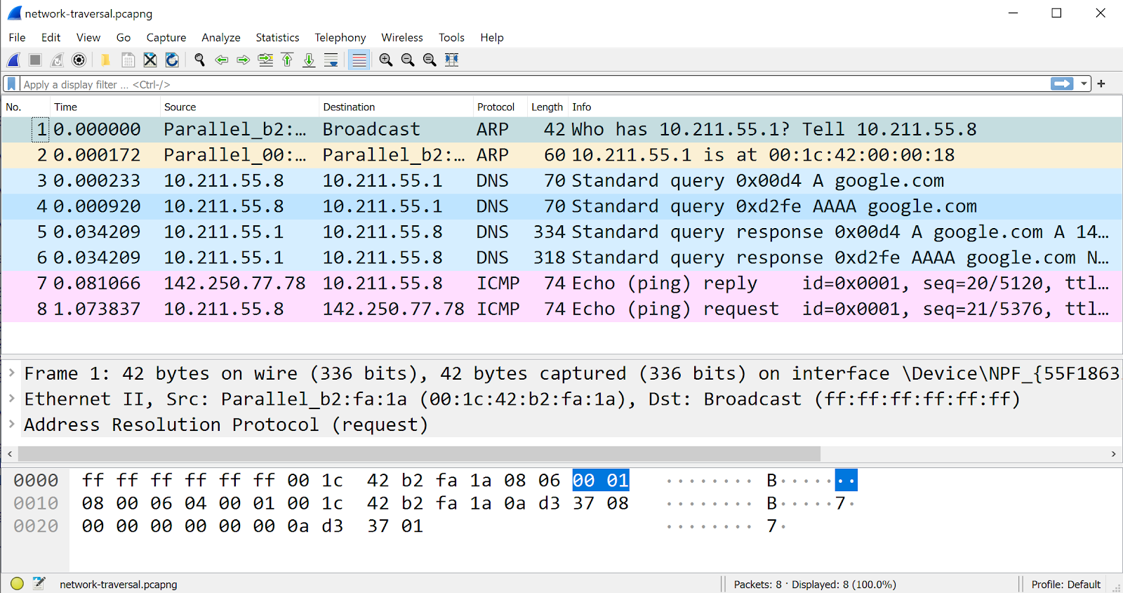
Figure 5: Packet traversal on ping to google.com
- G. Ping any other website, and ARP query for default gateway should not be seen since MAC address of gateway is already present in the cache. However, this entry will appear again on expiry of ARP cache, and same should be verified in wireshark capture.
Learning: Understanding of holistic view of network events triggered by a user action.
References
- RFC 768, “User Datagram Protocol”, Internet Standard, August 1980, https://tools.ietf.org/html/rfc768.
- RFC 791, “Internet Protocol: DARPA Internet Program Protocol Specification”, September 1981, https://tools.ietf.org/html/rfc791.
- RFC 793, “Transmission Control Protocol: DARPA Internet Program Protocol Specification”, September 1981, https://tools.ietf.org/html/rfc793,
- RFC 826, “An Ethernet Address Resolution Protocol”, Internet Standard, November 1982, https://tools.ietf.org/html/rfc826,
- RFC 1035, “Domain Name – Implementation and Specifications”, Mockapetris, November 1987, https://tools.ietf.org/html/rfc1035.
- RFC 2131, “Dynamic Host Configuration Protocol”, Droms, March 1997. https://tools.ietf.org/html/rfc2131.
- RFC 2616, “Hypertext Transfer Protocol – HTTP/1.1”, Fielding, Gettys, et al., June 1999, https://tools.ietf.org/html/rfc2616. :
- Ram Rustagi, “Experiential Learning of Networking Technologies: Understanding Network Layer and IP addressing”, journal of Computing and Communications, issue 02 – Vol 04: June 2020, “https://journal.accsindia.org/understanding-network-layer-ip-addressing/“
- Ram Rustagi, “Experiential Learning of Networking Technologies: Understanding IP Routing”, journal of Computing and Communications, issue 03 – Vol 04: September 2020, https://journal.accsindia.org/experiential-learning-of-networking-technologies-understanding-ip-routing-2/
- Ram Rustagi, Viraj Kumar, “Experiential Learning of Networking Technologies: Understanding TCP States Part I”, journal of Computing and Communications, issue 04 – Vol 02: June 2018, https://journal.accsindia.org/experiential-learning-of-networking-technologies-understanding-tcp-states-part-1/2/
- Ram Rustagi, “Experiential Learning of Networking Technologies”, journal of Computing and Communications, issue 01 – Vol 01: June 2017, https://journal.accsindia.org/experiential-learning/
- Kurose, Ross, “Computer Networking: A Top Down Approach”, section 5.7, 6th edition, Pearson.