
Most modern fighter aircraft are multi-role by design and rely heavily on a number of systems that are computer controlled in real time for achieving the most optimal performance. This paper presents three important real time control systems designed for the Indian Light Combat Aircraft. These are the flight control system, the anti-skid brake control system and the environment control system. Design objectives for these systems along with a description of their various hardware elements, software architecture and design concepts have been presented here. All the systems house extremely critical functions during different phases of flight, and so are designed for high degrees of reliability and extremely low failure probabilities. The concepts adopted for redundancy management, failure identification and failure handling are also presented.
1. Introduction
Modern fighter aircraft are designed for playing out multiple types of roles in battlefields, ranging from reconnaissance to ground attack to air-to-air combat. Often the roles undergo a switch from one to another during a single operation itself. To enable these multiple roles, aircraft depend heavily on several computer-controlled systems housed within it. Some of these are – flight control system, engine control system, steering and ANTISKID brakes control system, fuel control system, environment control systems, hydraulic and electrical control system, radar controls, weapon controls and so on. Each system not only has its own assigned role to play, but it is also often strongly connected with other systems as well. In fact, many a time the performance of one system heavily depends on the performance level of the other system, and its state of performance degrades considerably when the other system develops some failure. For example, the flight control system can perform its best only when the engine, hydraulics, electrical system etc. do not develop failures.
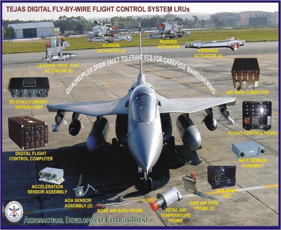
Indian Light Combat Aircraft (LCA) is a single-engine, tailless, delta-wing aircraft, which is longitudinally unstable. The aircraft has split elevons (two pairs) on the wing for pitch and roll control and a single vertical fin fitted with a rudder for directional control. The aircraft is also equipped with leading edge slats (LES) and a pair of airbrakes fitted, one each, on either side of the rear fuselage near the vertical fin. The flight control system (FCS) is a quadraplex, digital, full authority fly-by-wire system which receives inputs from the pilot stick and rudder pedals, aircraft motion feedback signals from quadraplex rate gyros (Roll, Pitch, Yaw) and accelerometers (Normal and Lateral). Redundant Total Pressure, Static Pressure, Calibrated air speed, Angle of Attack and Side Slip are used as inputs. FCS processes the inputs and using flight control laws (CLAW) implemented in the Digital Flight Control Computer (DFCC) controls the movement of the surface actuators during normal flying as well as under certain failure conditions.
LCA is designed as an unstable aircraft to improve its performance throughout the flight envelope, particularly in the supersonic regimes. However, the pilot cannot fly it without the aid of full-authority flight control system that actively stabilizes it. The stabilization is achieved using a set of complex control laws(CLAW) that control the movement of the aerodynamic control surfaces based on various sensor inputs. The pilot commands the aircraft to maneuver using a control stick located in the cockpit, but this stick is not directly connected to the control surfaces. It is electrically connected to the DFCC. CLAW interprets pilot inputs and enables the aircraft to perform the maneuver. CLAW design ensures that aircraft response is crisp and predictable throughout the flight envelope. CLAW also ensures that aircraft always stays within its prescribed flight mechanics and structural boundaries during all kinds of maneuvers.
While the flight control system controls the aircraft in flight, the aircraft also needs a good control system for optimal handling while taxing and during low and high-speed runs on ground. Two specific concepts that aid pilot significantly are the control over steering and braking. Aircraft that have a tricycle type landing gear arrangement need precise deflection of nose wheel angle to attain good steering. The maximum angle of steer is also dependent on speed: at very low speeds large steer angles are feasible, but as the speed increases the steer angles have to be limited significantly as otherwise aircraft can topple. The ANTISKID brake control is a much more complex design that allows for safe braking from very high speeds (>300kmph) to low speeds. In fact, ANTISKID braking is an absolute necessity because if the task of braking is left entirely to pilots, then any non-optimal brake pressure can cause tyre burst which is a very unsafe situation at high speeds. The ANTISKID brake control law design ensures that the pilot need not be cautious about applying brakes and the control system achieves optimal braking without any possibility of skidding and tyre burst.
The environment control system is another critical control system of the aircraft. It performs real time monitoring and control of the environment within the aircraft. It ensures temperature control of the cabin and maintains proper temperature for all critical electronic components inside. It also monitors and controls the pressurization inside the cockpit during flight. It interacts with several pressure and temperature sensors and controls the opening and closing of environmental control system air valves in different aircraft speed and altitude conditions. This system enables operation of aircraft from extremely low temperatures in the Himalayas to the dry desert heats of Rajasthan, to extremely hot and humid conditions in other regions.
This paper discusses real time control computations for three important systems implemented onboard LCA. The first part of the paper describes the flight control system in detail and presents its hardware and software architecture, its salient features that make it operate in real-time, and the various challenges that have been overcome to meet the desired high levels of safety and reliability. The second part of the paper describes the requirements of the brake management system, its hardware architecture, its software and various modes of operation. And finally, the third part of the paper describes the environment control system hardware and software architecture.
2. Flight Control System
LCA Flight Control System (FCS) consists of Digital Flight Control Computer, Sensors and actuators. It also incorporates a safety critical onboard flight program (OFP), which is real time onboard software. Identical software runs in parallel on four computers (called channels) within the Digital Flight Control Computer (DFCC). This software acquires the control input from pilot control stick assembly, Rudder Pedal Assembly and the current aircraft flight conditions from the air data system sensors. The FCS system Line Replaceable Units(LRUs) are depicted in Figure 1.
 The software performs redundancy management on the pilot input commands, aircraft rates, acceleration and air data inputs. These are the basic input to control laws which generate the aircraft surface position commands. LCA is an unstable aircraft, hence successful operation of the flight control system is critical for safety.
The system has a tight time window to gather data, process and update system. If the window is missed, then the stability of the aircraft can be degraded, and this reduced control can be catastrophic for an unstable aircraft. Additional complexity is due to the requirement of a very less probability of loss of controls (PLOC < 10-7 per flight hour). Being a safety critical system, FCS has been developed as a fault tolerant system too. This has been achieved by adding sufficient redundancy of its various subsystems in terms of quadraplex, triplex, duplex or simplex features depending upon their criticality. It is also essential that the health of the system is monitored continuously in a nonintrusive manner for achieving adequate levels of safety. In addition to this, as a confidence building test, the health of the system is checked by conducting a Pre Flight Built-In-Test (PBIT).
In the following sections we discuss real time control in the context of a closed loop embedded flight control system of LCA.
2.1 Hard Real Time FCS
A real time system is a system in which correctness of result not only depends on its logical correctness but also on the time at which the result is available. This time requirement is called deadline. In hard real time system, if the deadline is not met it could be catastrophic while in soft real time systems, beyond the deadline usage of the results decreases. So, in case of hard real time it’s mandatory to meet the timing deadlines while in case of soft real time it’s desirable. [1][2][3]
Flight control system falls under the category of hard real time system. Digital Flight Control System (DFCS) for a full authority fly-by-wire aircraft is designed and built to meet a variety of complex functions while having a very high degree of reliability. The need to meet the level of reliability that a simple mechanically controlled aircraft of yester years had increased the complexity of a FBW system in terms of need for redundant sensors, and actuators, and control through complex flight critical computer hardware & software.
The quad-redundant flight control computers manage redundant inertial sensors, flow angle sensors, air data sensors, pilot stick sensors, switches and other status discretes. They handle the control and redundancy management of state-of-the-art servo actuators. They interface with other sub systems of aircraft such as Mission Computer, Display Processor, Flight Test Instrumentation (FTI), Get U Home Panel (GUH), and Crash Data Recorder (CDR) etc.
FCS uses a DFCC that has high performance processors in quadraplex configuration. The identical software in each channel of DFCC is developed using a safe subset of Ada language and its identical copies are executed in all four channels of DFCC. Since FCS software is flight safety critical, strict process discipline is employed in its development by following well defined processes throughout the software development life cycle as per standards with Software Quality Assurance (SQA) and Software Configuration Management (SCM) to get reliable software product which is safe to fly.
The four channels of DFCC are identical but they are powered by four separate electrical power sources in aircraft. It embeds OFP software in all the four channels. DFCC receives inputs from all the hard-wired configuration items of FCS, uses the software to process them, and gives computed output signals to control the aircraft surfaces. It gives output to the display system in the cockpit and transmits data to the display and recorders. Each channel communicates to all other channels by way of cross channel data link. This allows the DFCC to support fault detection and a good signal selection. DFCC has channel failure logic for each channel. Channel failure logic is able to detect the failure of each computing channel. The channel failure logic disengages the failed channel.
The software incorporated in DFCC executes identically in all channels synchronously in hard real time. The computation in OFP consists of various logic, arithmetic, I/O intensive operations such as redundancy management of sensors, actuators. It also consists of optimized control flow design to meet best system performance, built-in-test and critical failures annunciation to pilot and computation of control law.
Some of the salient features of the system which play a vital role in real time control are as follows:
- Watch Dog Monitor
A Watch Dog Monitor (WDM) function is provided in each DFCC channel. The WDM provides fault detection for the digital processing function by requiring the CPU to issue refresh strobes on a regular and timely basis. Failure to provide this service results in a WDM time out, which constitutes a failure of the digital processing function for the affected channel. The WDM function does not share a common clock source with the CPU or any other signals upon which failure could result in a digital processing failure going undetected by the WDM. The WDM will be and remain in a failed state, which indicates a time out condition, upon power-up of a DFCC channel. It will be able to clear the WDM time out condition or failed state only after the CPU has issued the appropriate regular and timely refresh strobes. [3] - Cross Channel Data Link(CCDL)
This function performs the cross channel data communications between the four channels. The cross channel data link function transmits and receives all data in an encoded format. The CCDL function operates under the control of CPU. The CCDL function also provides several hardwired discretes between the DFCC channels for the purposes of synchronization. - Memories
Each channel of DFCC contains separate primary memories, scratchpad, NVM, Milbus-1553 Receive-Transmit, CCDL, D/A and A/D data memories [1]:
- The OFP memory is implemented using physically separate memories.
- Scratchpad variable data storage resides in volatile SRAM hardware.
- All 1553RT messages and data storage reside in1553B SRAM hardware.
- All CCDL receive and transmit data storage resides in CCDL SRAM hardware.
- All A/D data storage resides in SRAM hardware.
- All D/A data storage resides in SRAM hardware.
- All NVM data resides in NVRAM hardware.
2.2 Analog Module
The analog module provides servo electronics to control actuators with necessary monitoring circuits. Electronic circuits are incorporated for driving the solenoids, which control the flow of hydraulic oil into direct drive valves. Analog cards drive in-board and out-board elevon actuators on the left and right wings, midboard and out-board slat actuators on the left and right wings. Pulse Width Modulation (PWM) drives are used for better efficiency for driving DDV actuators.
The analog module also provides interfaces to FCS related sensors such as RSA, ASA and pilot command Linear Variable Differential Transducers (LVDT) and temperature sensors. CPU continuously monitors the salient parameters of the actuators control loop. Each channel of the DFCC contains circuitry, which provides conversion of analog signals for use by the software.
Each of the five primary actuators contains LVDTs at the DDV and actuator ram. The DFCC provides servo control electronics for each DDV and also receives the DDV position, DDV current, and ram position feedback from the actuator.
2.3 FCS Software Configuration
FCS software carries out the system’s overall operation. DFCC software processes the input signals, and controls the movement of actuators. The software includes functions of input data acquisition and redundancy management on the pilot input commands, aircraft rates, accelerations and air data inputs. The selected values of these parameters form the basic inputs to CLAW software for implementing a set of transfer functions, which generate commands for position of aircraft control surface. The surface position commands are then converted into commands to drive the primary and secondary actuators to move the control surfaces.
After the completion of initialization, the OFP enters into normal operational state. In this state the requirements for the real time operation are met. DFCC computation cycle starts upon entering into this normal operational state. Concept of minor and major window are used to define periodicity of the tasks. All essential functions are done once in minor frame. Each function is performed at least once in a major cycle.
In normal operational state the foreground functions are performed on receiving timer interrupt. Initially it performs WDM servicing. Then it performs the acquisition of A/D and discrete inputs and synchronizes all the channels. This ensures that real time processing of each channel starts executing at the same time. This is done to cause each channel to sample the input data at the same time. Normal control of the aircraft is done in this state. Mode engagement is checked. If there is no requirement to change the mode, the software resides in this state, process the inputs received, compute the CLAW, surface commands and process the output. The following are the sequence of operation performed by OFP:
- Service the watch log timer (real time interrupt).
- Acquire the input analog and discrete data.
- Transmit the self-channel data to other channels.
- Check for mode engagement.
- If mode engagement is not “BIT Mode” then it schedules other control mode function.
- Calculate the selected values of sensor data
- Compute the operational mode of the aircraft events and gain scheduling. The typical operational modes are ground roll/taxi, take off, up and away flight and approach and landing
- Based on event switching, the longitudinal/lateral/directional CLAW computation and elevon signal consolidation are performed.
- Generate surface commands and drive the actuators.
- Perform in-line monitoring for sensors and actuators.
- Fail detection and isolation of failed signals
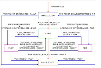
Figure 2: State machine for FCS software
Fault State
If there is any fault, it is identified during execution in any state and the software enters into fault state. It remains in this state waiting for ‘FCS RESET’ switch operation by pilot. On FCS RESET the channel will start from power up initialization. If it is healthy, this channel will complete initialization and enters into normal operational state. Figure 2 illustrates the software state machine.
2.4 FCS Design Challenges
Designing a flight control system and execution of the control algorithms in real time is a challenging problem. Some of these challenges are listed below.
- Computer Architecture:
Each DFCC channel includes processor, memories, input /output circuits, power supply unit and software. when a channel is declared failed, its link is cut and it neither processes any input nor sends out any output. FCS is designed so that the outputs of the failed channel are in the fail- safe mode when it fails. Failure detection is mainly achieved by comparing the difference between the control and monitoring commands which should be within a predefined threshold.
- Hard Real Time software:
Some of challenges in Onboard Software are: kernel working in the real time, synchronization of the 4 identical computers, managing the redundancy to ensure accurate inputs are sent to the Control Laws and the right commands are generated to drive the actuators, software controlled Built In Test for ensuring the health of the system before each flight.
- Failure Detection and Reconfiguration:
FCS has redundant sensors and for the proper redundancy management it is essential to detect the real failures while masking the nuisance failures. This is achieved by different techniques for comparison and isolation of the values within and across channels. Persistency time is used to ensure the failures are not nuisances. After failure detection the failed elements are isolated and system is re-configured to ensure that the system performance is achieved by the rest of the components.
- Actuator Control and Monitor
Actual surface position is compared to computed surface position using dedicated sensors. There are LVDTs installed in the actuators for sensing ram position and servo valve position which are used for this comparison and this helps in early detection of failure in actuators. Various current and voltage models are also implemented in software to predict the behavior of servo electronics so that faults in it can be detected and isolated.
- Deterministic constructs:
Programming constructs needs to be deterministic and all the dynamic allocation is prohibited because otherwise memory usage may become indeterministic.
- Getting the worst-case execution time:
As the logic in the software continues to grow and more complex algorithms get implemented that push the aircraft to its limits of performance like automatic recovery from low speed conditions or from critically low altitudes, the number of paths in software increase enormously. Initially it was tough to determine this worst-case time because execution time is a function of hardware architecture and the compiler performance and also good tools are not supported on the older hardware. Hence getting worst case time involved actual collection of data and accumulating the true worst case after removing the mutual exclusive conditions. However, these days with the availability of tools on latest hardware, it is easier to determine the worst-case path and predict computational time accurately.
- Interrupts:
On one side interrupts spoil the predictability of the system, but on the other hand a real time system needs to handle interrupts. Key feature of the design is that all the interrupts needs to be handled deterministically with proper interrupt handler and sufficient logging of data.
- Memory:
Amount of memory in embedded systems are limited so it is particularly important to track the usage of memory for each design cycle.
- Delays:
While delay loops are required in RTS, extra caution needs to be taken to ensure that these delay loops are deterministic and would end after fixed number of iterations.
- Input:
Acquisition of data from different sensors needs to be optimized. The sampling time of the signals needs to be chosen in a way that slow varying parameters are sampled less frequently compared to others.
- Conversion time:
Signal acquisition and conversions are autonomous so that other activities can be done while signals are getting converted from analog to digital domain.
- Recovery of failures:
Sometimes sensors or DFCC channels may fail transiently. For example, some electrical failure in the system may cause a particular sensor to fail, but as electric supply gets restored it can be brought back into usage. But it is crucial to objectively recover from failures, because if the failure situation still persists then such sensors/channels should not be recovered. Also, in certain situations, it is better not to recover from failures while the aircraft is in air. In these situations, such failed sensors are isolated, and signals are reset inhibited.
- Verification and Certification:
Flight Control System (FCS) being an essentially quadraplex system having numerous interfaces, its testing poses a special challenge. The test on this system at the integrated level covers the functions of not only the FCS hardware and the embedded software (OFP) but also the evaluation of the flyability of the entire control laws through various hardware-in-the-loop and pilot-in-the-loop simulation. This complex task, which is highly safety critical, uses test rigs such as Mini-Bird and Iron Bird. The Mini-Bird and Iron Bird rigs have the capabilities of supporting real time hardware/software incremental integration testing of Integrated Flight Control System (IFCS) and they integrate the redundant sensors, actuators, pilot stick, cockpit displays etc. When the real FCS hardware is not used for any reason, the same are simulated both for the hardware interface characteristics and their dynamics. The tests are devised in a highly planned manner and the test results are thoroughly analyzed before being put up for system certification.
3. Brake Management System of LCA Tejas Aircraft
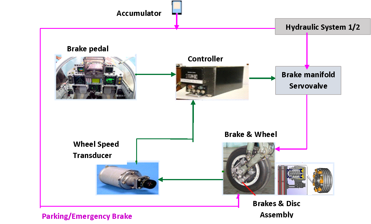
The main objective of the Brake management system (BMS) of LCA Tejas Aircraft is to produce optimum braking performance with minimum landing distance without wheel lock condition under various braking conditions. A microprocessor based controller namely BHEEM-EU (Brake control, Hydraulics, Engine and Electrical -Monitoring unit) is employed to control the operation of braking function with a dual redundant architecture, electrically as well as hydraulically. The wheel brakes are operated by foot pedals and the brake pressure demand is signaled electrically from pedals to servo valves through the microprocessor based controller.
3.1 System Requirements:
Brake management system is designed to meet the following requirements:
- The ANTISKID control law ensures to stop the aircraft in minimum possible distance without any wheel lock condition under various braking conditions like runway type, runway and tyre characteristics, braking speed, landing load and brake pad characteristics.
- Both wheels (LH and RH) are braked independently.
- Provision is built in the system to stop the rotation of wheels when the undercarriage is being retracted.
- Provision of the touchdown protection is built in the controller. i.e. it is possible to land with full foot pedal input without any possibility of wheel lock.
- Extensive self-testing, failure detection and reconfiguration capability is provided.
- In a degraded mode, with non-availability of anti-skid protection, it is possible to stop the aircraft safely with Direct Braking.
3.2 Controller hardware architecture:
The microprocessor based dual redundant controller provides for efficient brakes control and flexibility to change control functions. Each channel has a separate power supply, processor, memory subsystem and peripherals. The sensors and the final control elements are duplex. The input/output signal processing by the controller is also duplex. Normally channel1 will be active controlling the Brakes. In case of failure of channel1, channel2 takes over control which is in hot standby. The controller works with real time operating system and Ada language.
3.3 Modes of operation:
The control function operates in two modes namely ‘ANTISKID ON’ and ‘Anti Skid OFF’ mode, depending on the position of the mode selection switch selected by Pilot in the cockpit.
3.3.1 ANTISKID ON mode:
In the ‘Anti Skid ON mode’, ANTISKID control law is operational, and the algorithms are executed repeatedly at every 2.5 msec interval. The ANTISKID control schematic is as depicted in Figure 3. The controller receives the Brake pedal demand applied by the pilot and main wheel speed signals. Quasi slip is calculated based on acquired wheel speed and reference speed (in lieu of Aircraft speed) computed by the controller. Based on Quasi slip, the controller calculates the brake signal as per control algorithm and generates an output current signal to the Servo-valve which applies a modulated hydraulic pressure to the brakes depending on pilot demand.
Hence the controller will ensure optimum braking pressure to produce maximum friction coefficient between the tyre and the runway to ensure minimum stopping distance without leading to a skid on any runway condition, only if the pilot command exceeds the optimum brake pressure. The runway condition is interpreted through wheel speed data.
Failures related to the wheel speed signal will lead to loss of ANTISKID control indicating ‘ANTISKID FAIL’ in the cockpit. In this failure condition, braking will be available with switch in ‘Anti Skid OFF’ position as explained in Section 3.3.2. Total failures related to Hydraulics or pedal input or servo valve will lead to loss of brakes control indicating ‘BRAKE FAIL’ in the Cockpit. In this failure condition, Aircraft is to be stopped with Parking Brakes.
3.3.2 ANTISKID OFF mode:
In the anti skid OFF mode, the output current generated by the controller is in accordance to the pedal demand without anti skid protection.
3.4 Controller components:
The block diagram of the ANTISKID controller with various control components is as depicted in Figure 4. The control components and its description are as detailed below.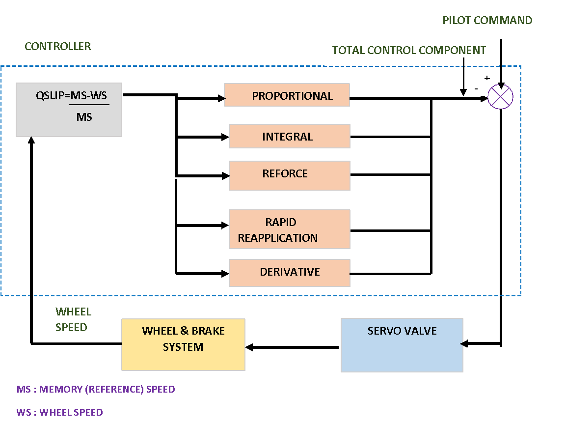
Figure 4: Block diagram of Anti-Skid Controller
- Proportional:
The proportional component controls the wheel from skidding during transient state of braking application by reducing the pressure proportional to quasi-slip.
- Integral and Reforce:
During the steady state of operation of the controller, it is the reforce and integrator components which continuously modulate the brake pressure about the optimum value. The integrator component decreases the brake pressure to suit the runway condition based on total quasi-slip computed over a period of time allowing the wheel to spin up. The reforce component slowly increases the brake pressure forcing the wheel towards skid condition. This results in oscillatory wheel speed response about the optimum value.
- Rapid reapplication:
The rapid reapplication component provides for fast increase in pressure so as to adjust the pressure when it changes from wet runway to dry runway conditions.
- Derivative:
Derivative control provides for quick reduction of pressure in anticipation of increase in quasislip.
- Total control component:
This is the sum of all the control components and is negative component. The control current to the servo valve is computed by the controller from the summation of pilot command and the total control component.
3.5 Redundancy management and safety features built in hardware:
- The controller is dual redundant. Inter processor communication is a continuous check to identify failure of any channel. In case of failure of channel1, channel2 takes over which is in hot standby. In case of failure of both processors of the controller, Analog braking is made available by the controller through Analog circuit which ensures brake pressure proportional to pedal demand with safe braking. In case of total failure of the controller channels, brakes are provided external to the controller with Parking brakes.
- Pedal transducers are redundant. Validity checks are provided for pedal inputs. If pedal input failure is detected by any channel, pedal input is copied from the other channel. Continuous comparison of pedal inputs is made across channels and if the difference exceeds a specified limit ‘Brakefail’ is declared.
- Dual coil Wheel speed transducers are connected to the two channels of the controller. Wheel speed coils are continuously monitored for open circuit/short circuit condition. Wheel speed as read by the two coils is also compared for fault detection. If wheel speed failure is detected by any channel, wheel speed is copied from other channel. If there is failure in wheel speeds as read by both channels, ‘ANTISKID fail’ is declared.
- Servo valves which modulate the brake pressure based on the input from the controller are dual redundant. Commanded and feedback servo currents are continuously compared and if their difference exceeds the threshold, ‘Servo valve fail’ is declared and control is changed over to other servo valve.
- Hydraulic system pressure to servo valves provided through Solenoid valves is redundant. If pedal is demanded and sufficient pressure is not developed or pressure is developed with Nil pedal demand with one Hydraulics system, ‘Hydraulics fail’ and ‘servo valve fail’ is declared and control is changed over to the other Hydraulics system.
3.6 Features of ANTISKID control law software:
3.6.1 Design features:
The ANTISKID braking software system is a safety-critical, embedded control system designed to meet real time schedule, provides fault tolerance and failure detection.
The software is developed with Vx Works Real time operating system (RTOS) and Ada programming language which are well suited for real time application. Vx Works RTOS features high performance, determinism, reliability, low latency, consistency and scalability. Ada language features strong typing, modular programming, run time checks, exception handling, portability, good readability, generics etc.
Modular software design is carried out and the various functionalities are realized with independent modules which provides the benefits of reusability, testability and ease of maintenance. The various modules used in ANTISKID braking software are depicted in Figure 5.
Fault tolerance is incorporated by designing the software to identify and handle exceptions. These detect an anomaly condition and provide a recovery path that permits continued system operation. Fault codes are generated by the module generating exceptions for further analysis and improvements.
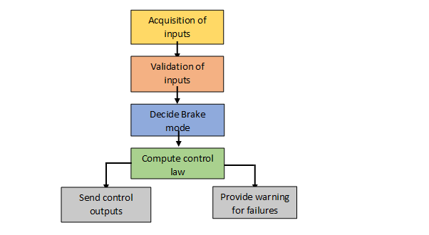
Figure 5: Modules of ANTISKID control software
3.6.2 Safety features built in software:
The following safety features are implemented in the controller.
- Rate limiters for pedal input: Rate limiters are provided for pedal inputs to avoid sudden increase in brake pressure and further skidding.
- Supervisory logic: On detection of quasi-slip>30% for 5msec, brake pressure to the wheel will be dumped fully to avoid instantaneous wheel lock.
- Cross wheel dump: If the difference in total control component between LH and RH wheel are greater than 15 bars, then 50% of the difference in control component is dumped to the wheel which is having a lower control component.
4. Environmental Control System
LCA is equipped with an Environmental Control and Fuel Monitor – Electronic Unit (ECFM-EU) which is an intelligent electronic control unit that performs real time monitoring and control of the environment within the aircraft. ECFM-EU primarily ensures temperature control of the cabin and the avionics bay, and performs monitoring and control of cabin pressurization in various phases of aircraft flight. It interacts with several sensor subsystems to acquire and process inputs, executes control algorithms to deliver the desired actuation whereby the requisite control of the environment and the fuel management is achieved. It controls the automatic opening and closing of environmental control system air valves and also provides override options to pilot to manually control these valves. Figure 6 shows the overall block schematic of the unit and various aircraft systems that it interacts with.
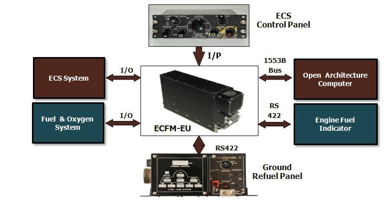
Figure 6: ECFM-EU interface block diagram
4.1 ECFM-EU Features and Software Organization
ECFM-EU is a dual redundant computer which is built around Motorola 68332 microcontroller. For display of system status and warnings it sends out information to the Open Architecture Computer (OAC) which is the Mission Computer. It also facilitates pilot manual override control of critical ECS valves through ECS CP located in the cockpit.
The entire ECFM-EU software is configured as one Computer Software Configuration Item (CSCI) and termed as ECFMEU – SW. It contains two top level Computer Software Configuration System (CSCS) namely SP software for acquisition of inputs / providing outputs and AP software for processing of monitoring and control algorithms AP Software runs on the MC 68332 Application Processor microcontroller and SP Software runs on MC 68332 System Processor microcontroller.
Each top level CSCS contains a number of low level CSCs called as a task (16 tasks in AP Software & 8 tasks in SP Software). Each Task includes a number of CSUS, each one called as a “Module”. Each module performs a unique function of the Task.
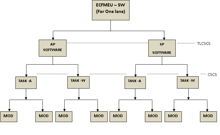
Figure 7: Software organization
4.2 System States and Modes
ECFMEU-SW operates in the following modes
- Short Power on self-test mode (SPOST)
- System Initialization mode
- Normal operational mode
- Long Power on self-test mode (LPOST)
- Ground test mode
The state transition diagram of ECFM-EU software is given in Figure 8
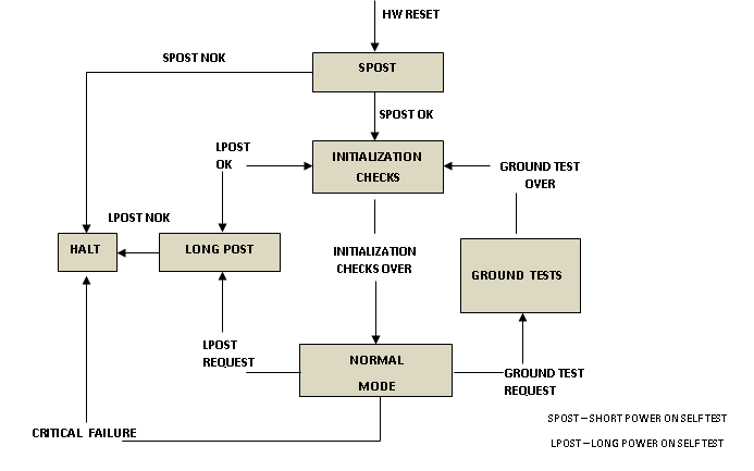
Figure 8: State transition diagram of ECFM-EU
4.3 ECFM-EU ECS Control Functions
A number of control functions are performed by ECFM-EU, some of the important ones of which are listed in the following subsections. These functions start functioning only if all the ECS valves are in their initial positions. If any ECS valve has failed, ECS control functions do not get performed.
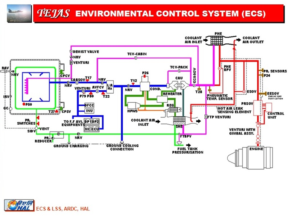
Figure 9: ECS system schematic diagram
4.3.1 Bleed Air Control
For environment control inside aircraft, compressed air is tapped out from the seventh stage of the compressor of the engine and this is known as bleed air. ECFM-EU controls and monitors five valves in Bleed Air control system.
- Bleed air is passed through a combined pressure reducing and shut off valve (BASOV). The pressure regulating function is achieved by pneumatic control. BASOV is controlled and monitored by ECFM controller.
- At downstream of combined PRV and BASOV, an Ejector Shut Off Valve (ESOV) provides the induced flow of ram air at Primary Heat Exchanger (PHE) and secondary Heat Exchanger when the aircraft speed is less than 0.4 mach.
- Engine Ejector Shut Off Valve (EESOV) supplies air for engine bay ventilation ejectors up to speed less than 0.4 Mach
- The bleed air is first cooled within the bleed control system in the PHE located in ECS bay, when the temperature is above 135 deg C. PHE By Pass Valve (PHEBPV), (pneumatic valve) bypasses the cooling in PHE when temperature is less than 145 deg C.
- The precooled bleed air is supplied to the ECS cooling pack through an ECS Shut Off Valve (ECSSOV).
Air for cooling pack temperature control and for cabin temperature control is taken from the downstream of ECSSOV. Air for fuel tank pressurization, AMAGB pressurization, Demist and canopy sealing are taken from upstream of the ECSSOV.
4.3.2 Temperature Control:
ECFM-EU controls and monitors two valves in this system.
Pre-cooled air enters the compressor of the Cold Air Unit (CAU) in the downstream of ECSSOV. At the outlet of compressor, pressure and temperature of the charge air increase due to compression. The charge air then passes through the SHE and then enters the High pressure water separation system comprising Regenerative Heat Exchanger, Reheater, Condenser and High pressure water separator. After these stages air enters the turbine of CAU. Air leaving the turbine is warmed to a controlled temperature level as it passes through the condenser and Liquid Air Heat Exchanger and will be delivered as cold and dry to cabin as well as avionics.
- The air tapped from the upstream of the compressor inlet of CAU is mixed with the cold air at the outlet of the turbine of CAU by Cooling Pack Temperature Control Valve (CPTCV). It avoids the ice formation at low pressure side of the condenser.
- The temperature of the air supplied to cabin is regulated by a Cabin Temperature Control system consists of a cabin temperature selector in ECSCP (T19), temperature sensors T17 and T27. These provide signals to the ECFM Controller to modulate the Cabin Temperature Control Valve (CBTCV) to maintain the selected cabin temperature.
4.3.3 Wind Screen and Canopy Demist:
Air bleed from the upstream of ECSSOV will pass through a demist valve, NRV and flow limiter to remove the mist on the wind screen and canopy. This can be done by operating Demist switch provided in ECSCP.
4.3.4 Avionics Bay Cooling:
ECFM-EU controls and monitors one valve in this system.
- The cooling air supply to avionics is taken from downstream of Liquid Air Heat Exchanger through Avionics Flow Control Valve (AVFCV) which control the flow based on temperature sensor T23 and the avionics heat load so as to limit the outlet temperature to avionics.
4.3.5 Cabin Seal Monitoring:
- The required pressurised air is taken from the upstream of ECSSOV. A combined (PRV, filter, NRV and relief) Valve provides necessary reduced pressure to the cabin seal via a seal inflation and deflation valve.
- The cabin seal is made out of silicon rubber to withstand high pressure and temperature. The seal will be inflated when the canopy is closed and locked. The seal will be deflated when the canopy is unlocked and when Cabin Ram Air Valve (CBRAV) is selected open through ECSCP.
- ECFM-EU monitors cabin seal pressurisation
4.3.6 Cabin Pressure monitoring:
Cabin pressure control is operated entirely by pneumatic means utilizing the differential pressure between cabin and external ambient. Cabin pressure controller valve will control the cabin pressure.
ECFM-EU monitors this system.
4.3.7 Cabin Ventilation System:
Cabin Ram Air Valve (CBRAV) can be opened through a switch on the ECSCP to provide cabin ventilation. It can be opened in the event of closure of ECSSOV or BASOV or CBSOV either due to the failure of ECS or intentional closure by pilot. When CBRAV opens cabin seal will be deflated automatically to allow free ventilation.
ECFM-EU does manual control of CBRAV through ECSCP and Monitoring
4.3.8 Air Supply for Fuel Tank & AMAGB Pressurization:
Air supply tapping is taken at downstream of PHE and upstream of ECSSOV to provide required air flow for fuel tank as well as AMAGB pressurization. This air passes through a small Heat Exchanger which is a part of SHE. The temperature of this air is controlled using Fuel Tank Bypass Valve (FTBPV) by ECFM-EU.
4.3.9 Cabin Shut Off Valve (CBSOV) control & monitoring:
Cabin Shut Off Valve (CBSOV) remains in the open state during the entire flight unless closed by pilot through manual override.
4.3.10 Leak Detection System (LDS) check:
During initialization checks & when engine RPM reaches 60% Leak Detection System (LDS) is to be checked. An initiate LDS BIT drive is to be given to perform this check.
4.4 ECFM-EU Redundancy Management:
- Dual lanes Redundancy Management:
ECFM-EU is dual redundant controller with two lanes: Lane1 & Lane2.A lane changeover is affected on occurrence of Lane1 (active lane) failure, if the standby lane is healthy. After a successful lane changeover, the standby lane becomes the controlling lane and the other lane is declared as failed one. The failed lane then stops all its activities and goes to an idle mode. The lane changeover is affected only if any of the following condition is satisfied in active lane and Standby lane is healthy:- CPU failure
- Memory failure
- Clock failure
- Power supply failure
- AP-SP link failure
- DPRAM (inter lane interface memory) check
- 1553B RT memory (Mission computer interface memory) check
- Dual sensors data handling:
Active lane’s sensor data is used by standby lane for processing till active lane sensor fails. When active lane sensor fails, standby lane’s sensor data is used for processing by active lane and standby lane. When active lane itself fails, standby lane’s sensor data is used for processing by standby lane.
4.5 Real Time Computation:
ECFM-EU interfaces with various ECS system analog signals (temperature sensors & pressure sensors) & Discrete signals (switches and valve feedback) to acquire and process the inputs. It executes ECS control algorithms iteratively to drive various ECS system valves whereby the requisite control of the environment is achieved. It also monitors ECS system signals & valve operations for the required conditions as per the ECS control algorithms and sends display parameters & warnings to open architecture computer for cockpit display. It is an iterative process and it repeats the various ECS control and monitoring functions, during every iteration.
The analog signal inputs are multiplexed using an 8 channel multiplexer and are then read through a 16-bit A/D converter. The discrete signal inputs have to be read by ECFM-EU and debounced properly before they are used ECS control algorithm.
The valve drives are generated using the Low Side Drivers (LSDs), High Side Drivers (HSDs) & H-bridge Drivers (HBDs) hardware. A few ECS system valves are driven through Microcontroller’s Time Processor Unit (TPU) channel for incremental valve operation for the required time period. It is a 32-bit Micro controller running at 16 MHZ clock speed. It has 16 independent TPU channels and two timer counters. TPU channel is configured in Queued Output Mode (QOM). TPU channels generate the required timing and LSDs/HSDs are the ones, which drive the valves.
Moving average of eight samples of the acquired analog signals is done by the Electronic unit in order to filter out the noise. The analog signals are validated by checking for their range. If a signal is found to be out of its range for more than the specified persistence time, it is not used for ECS control algorithm.
4.6 Failures Handling Aspects of Software Architecture:
On power up ECFM-EU completes Short Power ON Self-Test (SPOST) to determine the availability of the LRU functionality. The results of the SPOST are communicated to Mission computer for display in the cockpit.
Following checks shall be carried out during SPOST in 5 seconds:
- CPU check
- Data memory (RAM) check
- Program memory (FLASH) check
- DPRAM (inter lane interface memory) check
- 1553B RT memory (Mission computer interface memory) check
- Lane change over circuitry check
- AP-SP communication (inter processor) link check
- Power supply check
At the end of SPOST, if no failures are encountered then that lane is declared healthy. If both lanes are healthy Lane 1 is declared as ‘ACTIVE’ and Lane2 is declared as ‘STAND BY’. If lane is healthy, then it gets in to Normal mode of operation to perform initialization checks. In case of occurrence of any failure during above self-tests, the software commences fault logging and subsequently halts the processor.
Initialization checks are carried out on the successful completion of SPOST. This includes the following checks:
- Sensors check
- A/D converter check
- Leak Detection System Initiate BIT check
- ECS-CP Switches position check
- Valves drive check
- Valves Initialisation check
In case of occurrence of any failure during above initialization checks, the software commences the fault logging. After completion of initialization checks, system performs ECS control algorithm processing iteratively.
Continuous Built In Test (CBIT) is performed iteratively during Normal mode of operation by ECFM-EU.
Following checks are carried out during CBIT:
- AP-SP communication (inter processor) link check
- Data memory (RAM) check
- Program memory (FLASH) check
- 1553B RT memory (Mission computer interface memory) check
- Sensors checks
- Power supply check
In case of occurrence of any failure (other than e) during above CBIT, the software commences the fault logging and stop servicing the watchdog, there by achieving the required lane change over.
The module also checks for the health of RT (ECFM-EU) and if there is a 1553B bus silence it declares that the communication with Mission computer has failed and start using Mission computer data of other lane.
ECFM-EU enters in to Flight Line Maintenance Mode of operation, on request from aircraft maintenance crew through the mission computer (Long POST request). During this mode of operation, it performs various long duration power on self-tests (Valve checks) and outputs the test results to the mission computer. On successful completion of these tests, it re-initializes the system.
In case of occurrence of any failure during above self-tests, the software commences the fault logging and subsequently halts the processor.
Conclusions:
This paper describes three critical real time control systems implemented on Indian LCA Tejas. Flight control system, brake management system and environmental control system undergo rigorous testing in the rigs before implementation on the aircraft. The systems have also been extensively tested during flight tests on the aircraft. The flight control system has gradually expanded its envelope from the lowest flyable speed end to the supersonic high speed end, from the negative to the highest safe angles of attack and in terms of achieving -3g to +8g normal acceleration. Flight control system has performed very well also with all possible store configurations. The flying qualities of the aircraft has won appreciation of all the pilots who have tested and flown the aircraft. The brake management system has been extensively evaluated at rigs and on aircraft at low and high speeds, low and high aircraft mass and various pedal inputs and has been found to be satisfactory. It is also evaluated on wet runways and during high speed rejected take off conditions and has been found to be satisfactory. Likewise, the environment control system has undergone rigorous testing in rigs and during flight tests, and has contributed significantly to proper functioning of all aircraft systems at extreme cold and hot temperature conditions.
References
[1] A. Gambier, “Real-time control systems: a tutorial,” 2004 5th Asian Control Conference (IEEE Cat. No.04EX904), Melbourne, Victoria, Australia, 2004, pp. 1024-1031 Vol.2
[2] Stuart Bennet, “Real-time Computer Control: An Introduction”, Prentice-Hall international series in systems and control engineering, ISSN 0892-4252., 1994
[3] Jane W. S. Liu, “Real-Time Systems”, Prentice Hall, ISBN 0130996513, 9780130996510, 2000
Acknowledgements
Authors would like to acknowledge the contributions from DRDO labs like ADA, ADE, RCMA, CRI, HAL and a number of Indian Air Force Pilots for their direct or indirect support.