In any TCP-based client-server communication, the application layer is implemented in the application program whereas the transport layer (i.e., TCP protocol) is implemented in the underlying operating system. TCP achieves reliability using acknowledgement packets and retransmitting any packets that are lost in the network, or corrupted, or delayed or delivered out-of-order. In addition, the TCP protocol ensures that the receiver application is not overwhelmed by data from the sender application — only the amount of data that the receiver can consume is transmitted. This is called TCP Flow Control. In this article, we explain the basics of flow control and provide experiential learning exercises to help understand its impact on TCP performance.
In the last 3 articles [4][5][6], we have discussed scenarios of TCP communication and data transfer in general, TCP connection setup and tear down, and how TCP behaves under different network conditions. We have also defined various conditions that occur in the network, and ways to diagnose these conditions and address them. Once the TCP connection is setup and data transfer starts, the performance of TCP (in terms of throughput achieved) varies based on network conditions. In this article we will discuss Flow Control — an aspect of TCP behavior that influences data throughput in a connection.
When a TCP client (e.g. web browser) connects to a TCP server (e.g. web server), and a successful TCP connection is established between them, the client sends the request (URL) and the server sends the response (web page) back. When the response size is large (e.g., downloading a large file), the server (sender) would like to know the optimal rate at which it can send data to the client (receiver). If the server sends data at a higher rate than the receiver can receive and consume, overflow will occur at the receiver and excess data will be discarded. This would force the server to retransmit the data again. If the server sends the data at a lower rate, then it will take longer than necessary for the receiver to receive the entire data. Thus, both cases lead to sub-optimal performance. TCP protocol provides a mechanism for optimized delivery called flow control. In simple terms, flow control means that the receiver controls the rate at which the TCP sender sends the data. This rate is primarily determined by the size of the TCP buffer allocated at the receiver’s side. Whenever the receiver application issues read requests, the TCP stack supplies data to the application from this buffer, so the key question is: how large should this buffer be? When the receiver processes requests the underlying operating system for a buffer, it risks allocating a buffer of sub-optimal size. If the allocated buffer size is too small, it will rapidly overflow: the receiver will be forced to discard these overflow packets, and the sender would be forced to wastefully resend these packets. If the allocated buffer size is too large, this may prevent other applications from running on the same host simply because resources have been allocated wastefully. Since a fixed buffer allocation strategy is problematic, the receiver needs to be flexible with its buffer allocation and dynamically change the buffer size in response to application characteristics as it consumes data over the TCP Connection. This aspect of TCP optimizes flow behavior. We now discuss the process by which the TCP protocol adjusts over time to achieve flow control.
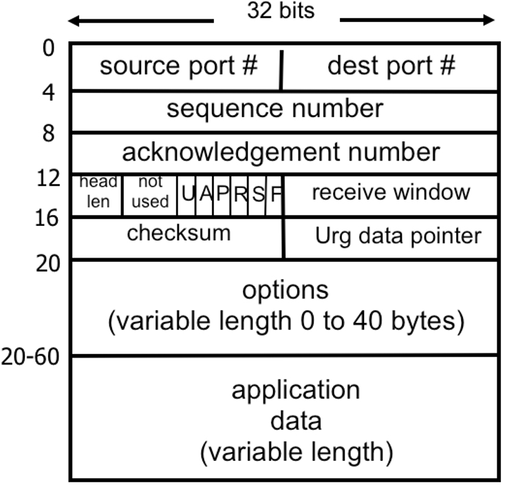
To enable TCP to implement flow control, the receiver informs the sender about the size of the buffer it has allocated during the connection setup. TCP supports this feature via its header field “receive window”, a 16-bit long field at an offset of 14 bytes in the TCP header (Figure 1). For a detailed understanding of TCP headers, the reader is directed to the TCP standard RFC 793 [1]. With 16 bits, the maximum buffer size is just 64 KB. With today’s high-speed networks and easy availability of large memories, this 64 KB limit is far too restrictive and needs to be enhanced. This has been achieved by making use of the TCP Window Scale option [2][3] which specifies a scaling factor by which the receive window size is multiplied. Thus, the maximum value of the TCP receive buffer can be as large as 1 GB [2][3].
The TCP protocol follows pipelined communications: the sender transmits one data segment after another without waiting for each ack, subject to the condition that total size of data segments sent is less than the receiver’s buffer size. Whenever the receiver receives a data segment, it sends an ack, which follows the process of cumulative acknowledgement1 . Further, TCP is a streaming protocol and thus acknowledgement is at the byte-level and not at the segment-level. For a better understanding of TCP sequence number and acknowledgement number fields (fields 3 at offset of 4, and field 4 at offset of 8, the reader should refer to [4][9], where TCP streaming and reliability are discussed along with experiential learning exercises.
An excellent interactive resource for a basic understanding of flow control is available [7]. For a more detailed understanding of its implementation using receive window buffer management, let us consider a scenario where the sender needs to transmit 10000 bytes of data. For simplicity, let us assume that the receiver has a buffer of size fixed at 4000 bytes (in reality, this buffer size is dynamically adjusted as per communication needs). Further, let us assume that the sender transmits 1000 bytes every 5 seconds whereas the receiver processes (consumes) 800 bytes every 8 seconds.
The status of the receive window size each time the sender transmits data and the receiver acknowledges the same is shown in Figure 2. The following color coding has been used for ease of understanding: Black denotes TCP data transmitted by the sender, blue denotes TCP ack from the receiver, green denotes an update (decrease) in the rwnd (Receive Window) value when data is received from the sender and an ack is sent, and purple denotes an update (increase) in the rwnd value when the receiver application reads the buffer and thus makes some space available. (When rwnd=4000−krwnd=4000−k, it means that kk bytes of data are already filled in the buffer and waiting for the application to read).
The sender first establishes a TCP connection with the receiver by performing a 3-way handshake (first 3 messages in Figure 2) [5]. The receiver informs the sender during the connection setup that its receive buffer size rwnd is 4000 bytes, as shown in Figure 2. After the successful connection setup, the sender begins transmitting 1000 bytes of data every 5 seconds: T0,T5,T10,…T0,T5,T10,… etc. The TCP stack at the receiver sends the ack for each data segment by appropriately updating its rwnd value to indicate the memory available in the receiver’s buffer for this connection.
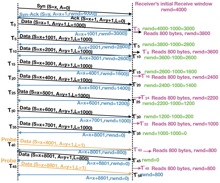
During the connection setup, the sender is informed that the receiver can receive up to 4000 bytes of data at a time. Thus, at time T0T0, the sender transmits 1000 bytes as it can transmit up to 4000 bytes. The receiver receives this data at time T’0T’0 (slightly after T0T0, because of transmission delay and propagation delay [8]), stores it in the buffer and updates rwnd to 3000 (4000 – 1000). This updated value is communicated to the sender via the ack. Since the application at the receiver is waiting for data that is now available, it immediately reads 800 bytes from the TCP buffer and starts processing it. This frees 800 bytes from the buffer and hence rwnd is updated to 3800 (3000 + 800). Note that 200 bytes of data are still in the buffer, waiting to be read by the application. At time T5T5, the sender transmits the next 1000 bytes of data. Once again, the receiver stores this data in the buffer and returns the updated value of rwnd = 2800 (3800-1000) to the sender via the ack. This pattern continues, with the value of rwnd eventually decreasing to 0 after the sender transmits 1000 bytes at T35T35.
At this point (T35)(T35), the sender cannot transmit any more data since it has received an ack with rwnd=0, indicating that the receiver’s buffer is full. In the scenario we are considering, the application will read 800 bytes from the receiver’s buffer and update rwnd to 800. However, the receiver cannot send a duplicate ack (this can lead to other implications on TCP connections). Thus, both the sender and the receiver appear to be stuck. This deadlocked scenario is generally known as “TCP Zero Window” [10][11], and it can lead to severe performance issues. Exercise 3 describes an experiment to better understand this phenomenon.
[ 1 ] Cumulative acknowledgement means that when the ack value (3rd field in Figure 1 ) is NN, it implies that it has received all the data up to byte number N−1N−1. This implies that even if TCP segments containing ack values N−kN−k (for one or more values of k≥1k≥1) are lost, the ack value of NN in a subsequent packet implies all data up to byte N−1N−1 has, in fact, been received.
Fortunately, TCP provides a mechanism to deal with Zero Window: the sender can periodically transmit a Zero Window Probe (ZWP) message, which could be as small as a single byte of data. Once the receiver gets this TCP message from the sender, it must respond with an ack. Thus, if a ZWP is received after rwnd has been updated to a positive number, the receiver can indicate to the sender that its buffer is no longer full in the ack. Two ZWPs are shown in yellow in Figure 2. The first of these probes is initiated at time T40T40. If we assume that the application clears 800 bytes from the reader’s buffer before this probe arrives at time T’40T’40, the resulting ack will indicate a positive rwnd value — as shown here. In contrast, consider the second probe initiated at time T45T45. In this case, there still isn’t any free space in the reader’s buffer and hence the ack reports that the value of rwnd is still 0. One or more additional ZWPs (not shown) would have to be issued before data transmission can continue.
ZWPs are used in many other networking applications. For example, consider a network printer that prints documents sent from the machines it is connected to. Since the printer has no data to send, it is the receiver. Suppose that the printer runs out of paper and it takes several minutes to replenish the paper stock. During this interval, the printer may continue to receive documents (without actually printing anything) until its buffer is full. In this case, it will send an ack with the value of rwnd = 0 to the sender machine. This machine can periodically send ZWPs to the printer, and as soon as the paper stock has been replenished, it will resume printing by consuming the data from the receiver buffer. At this point, the value of rwnd will become greater than zero and the ack for subsequent ZWPs will indicate that the printer is ready to receive new documents.
Alert readers may have noticed a potential problem with this seemingly neat mechanism: an adversary can launch a Denial of Service (DoS) attack [11] by opening connections to a server (sender) and immediately responding with rwnd = 0. This would force the server to waste resources by sending ZWPs (the attacker would respond to each ZWP with rwnd = 0), thus creating a DoS attack. To thwart such attacks, the server follows the standard TCP exponential backoff mechanism where the interval between successive ZWPs doubles each time, up to a pre-configured maximum number of retries. If this limited number of retries is exhausted, the TCP connection may be closed prematurely, releasing resources and avoiding DoS attacks. We now describe a real-life instance where this issue occurred while the first author of this article was managing the cloud deployment of servers.
In this scenario, end users needed to download the roughly 2.5 GB Android image of a mobile phone over a 2 Mbps to 4 Mbps link. In contrast, the servers were interconnected via a Gigabit Ethernet network, as shown in Figure 3. User connections terminated at the Load Balancer (LB), and the LB would initiate a new connection to the Web Server (WS). The WS, in turn, would connect with the Application Server (AS) and Data Store (DS). Thus, for a single download interaction for end-user UU, the LB would be dealing with two TCP Connections: a connection TCPUTCPU where the LB was the sender and UU was the receiver, and a connection TCPWSTCPWS, where the WS was the sender and the LB was the receiver. When the download was initiated, the WS could pump data at a very high rate over TCPWSTCPWS, whereas data was consumed by the user UU at a far lower rate over TCPUTCPU.
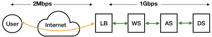
In order to store as much data as possible from the WS, the LB was forced to rapidly increase its receiver buffer size for TCPWSTCPWS (by requesting more memory from the OS) until it reached its maximum. This buffer was emptied by copying to the buffer for TCPUTCPU, but this occurred at a very slow rate. Due to the huge bandwidth available for TCPWSTCPWS, the WS received an rwnd value of 0 from the LB even after multiple ZWPs. When the retry threshold was exceeded, the connection TCPWSTCPWS was terminated with about 0.4 GB unsent to the LB. Thus, the end-user was unable to download the entire image.
When this problem was reported in the field, the engineering team responded, as it should by proposing probable causes, based on prior experience and the available data. Suspicion initially fell on the AS application, and when no fault was discovered, the analysis proceeded further. Eventually, and only because of a clear understanding of the TCP Zero Window issue, the problem was diagnosed correctly. (If the first author’s role with the team had not ended shortly after this, the next task would have been to examine strategies for fixing the issue — such as reconfiguring the maximum number of ZWP retries and/or timeout values — and rank these based on the available resources.)
For an experiential understanding of TCP Flow control, reader should follow the steps as defined in Exercise 1 and Exercise 2.
TCP flow control ensures that the receiver is not overwhelmed by data from the sender. In contrast, the User Datagram Protocol (UDP) does not support flow control. Over a UDP connection, the receiver can become overwhelmed and will be forced to drop some of the transmitted data.
Flow control is one of the two key mechanisms that govern TCP performance — the other mechanism is Congestion Control. We will examine Congestion Control in detail in the next article, but briefly it is a mechanism that allows the sender to discover a near-optimal rate at which data can be transmitted over the TCP connection, keeping in mind that network capacity can vary significantly over the course of the data transmission. If the sender transmits data at an excessively low rate, it will be under-utilizing the network capacity and will take more than the optimal time to transmit the entire data. On the other hand, if it sends data at a higher rate than what network can sustain, it will choke the network. As a result, packets will queue up in the network at various stages when buffers become full, some packets will be dropped by intermediate network devices, such as routers, and this will lead to higher queuing delay and wasteful retransmission of packets.
Even though both congestion control and flow control deal with different error conditions, they have the same objective of improving TCP performance and the response of the TCP implementation in both these error conditions is the same — retransmit lost/corrupted/discarded/delayed data segments. Thus, a common misconception is to consider these as equivalent conditions. However, as we shall see in the next article, they are quite different and should be understood differently.
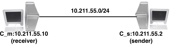
All the exercise steps described assume that two machines, namely, Client (C_m) and Server (S_m) are connected via a network. An example of this connectivity is shown in Figure 4. The client machine C_m is an Ubuntu Linux and server machine could be any machine (Ubuntu/MacOS/Windows) etc. To understand the flow control behavior, two simple Python programs (to be run with python3) are provided: one for the client (accsclient.py), which will connect to the server and simply receive data, and the other for the server (accsserver.py), which will accept connection from the client and send data. These programs are listed in the Appendix.
Topic: Basic understanding of TCP Flow Control with default setup i.e. with Window Scaling
python3 accs_server.py -b 200 -d 1 -p 9999sudo tcpdump -n -i enp0s5 host 10.211.55.2 and port 9999python3 accs_client.py -s 10.211.55.2 -p 9999 -b 100 -d 2 -c 1000win field and it is likely to increase with each packet received from server. Given below are sample output for first 4 capture outputs of packets sent from client to server. Notice that win field value starts increasing slowly. The value of ack field is consecutively as 201, 401, 601 etc. i.e. increases by 200 each time indicating that 200 bytes are received. Since data is continuously received, TCP stack slowly increases the client receive buffer size as well. 20:09:21.091424 IP 10.211.55.10.60892 >>Topic: TCP Flow Control with Window Scaling disabled.
$ sudo sysctl net.ipv4.tcp_window_scaling net.ipv4.tcp_window_scaling = 1$ sudo sysctl net.ipv4.tcp_rmem net.ipv4.tcp_rmem = 4096 87380 6291456$ sudo sysctl-w net.ipv4.tcp_window_scaling=0 net.ipv4.tcp_window_scaling = 0$ sudo sysctl -w net.ipv4.tcp_rmem="4096 4096 4096" net.ipv4.tcp_rmem = 4096 4096 4096$ sudo sysctl net.ipv4.tcp_window_scaling net.ipv4.tcp_window_scaling = 0$ sudo sysctl net.ipv4.tcp_rmem net.ipv4.tcp_rmem = 4096 4096 4096 These TCP Tuning parameters are set only temporarily and if machine is booted, TCP will start with its default value.win field in tcpdump.Topic: TCP Zero Window Probe.
$ sudo sysctl -w net.ipv4.tcp_window_scaling=1$ net.ipv4.tcp_window_scaling = 0$ sudo sysctl -w net.ipv4.tcp_rmem=" 4096 87380 6291456" net.ipv4.tcp_rmem = 4096 87380 6291456Client program: accs_client.py.
#——————————————————————————–
#!/usr/bin/python3
import socket
import time
import argparse
parser = argparse.ArgumentParser
(description=
“Simpleâ£Serverâ£forâ£N/wâ£Delays”)
parser.add_argument(’−−s’, ’−−−−server’,
type=str, required=True)
parser.add_argument(’−−p’, ’−−−−port’,
type=int, default=9999)
parser.add_argument(’−−c’, ’−−−−count’,
type=int, default=10)
parser.add_argument(’−−d’, ’−−−−delay’,
type=int, default=5)
parser.add_argument(’−−b’, ’−−−−buffer’,
type=int, default=50)
args = parser.parse_args()
ip_addr = args.server
port = args.port
count = args.count
delay = args.delay
buffer = args.buffer
srvr_addr = (ip_addr, port)
sock = socket.socket(socket.AF_INET,
socket.SOCK_STREAM)
sock.connect(srvr_addr)
for i in range(1,count):
data = sock.recv(buffer)
print (“received:”, data)
time.sleep(delay)
sock.close()
#——————————————————————————–
Server program: accs_server.py.
#——————————————————————————–
#!/usr/bin/python3
import socket
import time
import argparse
parser = argparse.ArgumentParser
(description=
“Simpleâ£Serverâ£forâ£N/wâ£Delays”)
parser.add_argument(’−−s’, ’−−−−server’,
type=str, default=”0.0.0.0″)
parser.add_argument(’−−p’, ’−−−−port’,
type=int, default=9999)
parser.add_argument(’−−d’, ’−−−−delay’,
type=int, default=1)
parser.add_argument(’−−b’, ’−−−−buffer’,
type=int, default=100)
args = parser.parse_args()
ip_addr = args.server
port = args.port
delay = args.delay
buffer = args.buffer
sock = socket.socket(socket.AF_INET,
socket.SOCK_STREAM)
srvr_addr = (ip_addr, port)
sock.bind(srvr_addr)
sock.listen(5)
connsock, client = sock.accept()
print(“receivedâ£aâ£connâ£from”, str(client))
while True:
msg = “A” * buffer
print (“Sending:”, msg)
sent = connsock.send(msg.encode(’ascii’))
time.sleep(delay)
#——————————————————————————–