
The transport layer in a network stack provides end-to-end connectivity to the application layer. In the internet stack, there are two main transport layer implementations in use: TCP (which provides reliable service delivery) and UDP (which does not). Unfortunately, many people misconstrue these characterizations as “TCP provides guaranteed delivery” and “UDP may make errors”. This article attempts to clarify such misconceptions. It also discusses practical aspects of these two protocols (including TCP’s streaming service and UDP’s message-oriented service) and illustrates concepts with simple hands-on exercises.
The transport layer in the TCP/IP stack provides end-to-end connectivity between applications on two machines, which could be located anywhere in the world. For example, when a user accesses google.com in the browser, it establishes a reliable TCP (Transport Control Protocol) [1] connection between the user’s browser and one of Google’s servers. The TCP layer makes use of the underlying IP(Internet Protocol) [3] layer in the network and provides the required transport services to the application layer (e.g. HTTP [4]), in order to deliver usable data to the applications involved.
At its core, the Internet only provides the IP layer, which in turn only provides “best effort delivery”. It is important to note that “best effort delivery” does not provide any guarantee that a given packet will be delivered (or even that it will be delivered within a certain time-frame). It is quite possible that the IP layer loses some packets, and it does not retransmit such lost packets. Thus, IP does not provide any service guarantee with respect to lossless service. Further, since different IP-layer packets may traverse different paths between the same source and destination (on account of routing changes and updates in the IP network), these packets may be delivered out-of-order at the destination. Similarly, the IP layer does not guarantee that delivered packets will not be corrupted. Error detection at the IP layer is limited only to IP packet headers, whereas the data in the packet may get corrupted. Thus, a useful analogy for “best effort delivery” is postal delivery to a difficult-to-reach location. While the postal service promises its best effort, mail to a recipient may get lost or damaged on the way, and letters to the same address may arrive out of order.
Thus, even though the IP layer provides best effort delivery of packets given to it, it is the responsibility of the transport layer to provide some sort of reliability while depending upon underlying unreliable IP layer. Once again, the postal analogy is helpful. If the postal service discovers that a letter cannot be delivered due to an incorrect destination address, it tries to return the letter to the sender. Similarly, the receiver may confirm receipt of the letter via a letter in reply.
The transport layer helps two applications maintain the illusion that they are directly connected (a logical connection), even though the physical connection between them may consist of a number of intermediate network devices such as switches, routers, firewalls, etc. In any communication, the sender application breaks the data into segments (known as packets at the transport layer). The transport layer is responsible for delivering these packets to the receiver application, as per expected service delivery.
The two most commonly used transport layer protocol implementations for the Internet are transport Control Protocol (TCP) and User Datagram Protocol (UDP). Both of these differ significantly in the way they provide data delivery to applications.
UDP provides unreliable, connectionless and message-oriented service to applications that use it. In contrast, TCP provides reliable,connection-oriented, streaming, and in-order delivery service to applications that use it. When an application hands over transport layer packets to UDP, it is generally called a datagram. (At times, this term is also used for packets at the network-layer Internet Protocol, or IP). Similarly, a transport layer packet to TCP is generally referred to as a segment.
We will discuss each of the italicized terms above, as well as packet corruption and error control. For experiential understanding of these concepts, we will use the nc (Netcat) tool [5] and some simple Python programs. The Python programs for both the sender and receiver using both TCP and UDP along with instructions for their usage are available at [6]: udp_client.py, udp_server.py, tcp_client.py, and tcp_server.py.
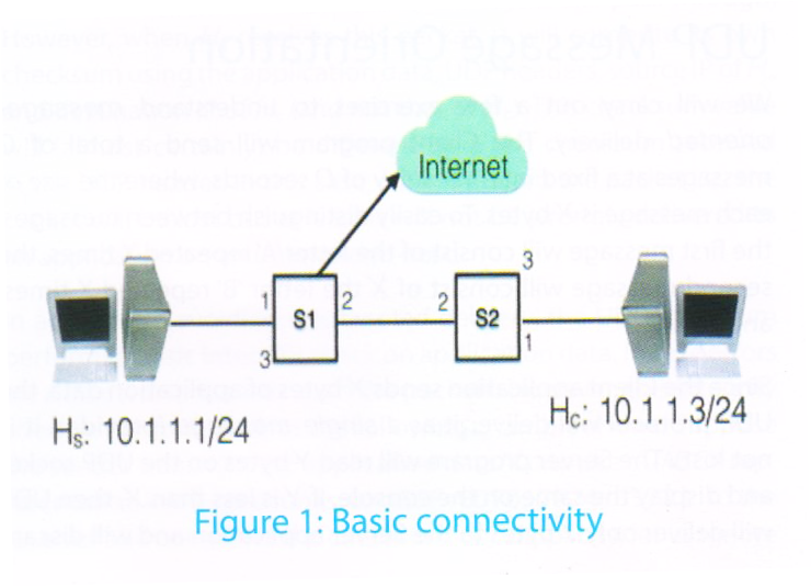
The basic setup for the exercise that follow involve two systems (laptops, desktops, etc.) connected via a network consisting of two simple (unmanaged) switches, as shown in Figure 1. This is the simplest possible representation of the internet/network that allows us to introduce disturbances (such as network breakdown) without the applications being directly aware of them. The applications rely only on the transport layer protocol that provides the end-to-end logical connection. The internet connectivity shown here is not mandatory, but it represents a typical setup where users would like to remain connected to the internet while carrying out these experiential learning exercises.
An application at the transport layer needs transport layer addresses (port numbers). The Server program would run on a known (published) port number, which the Client program needs to be known. By default, the port for the Server is taken as 9999, but this can be changed using the option -p for both the TCP and UDP versions of the Server program.
UDP is the simplest transport protocol in terms of implementation and delivery, It is a no-frills/bare-bones transport protocol that simply takes the application message data (maximum size of 64KB) from the sender application and tries to deliver the full message in one go to the receiver application. It will deliver this message in full, and not in multiple parts. It is up to the application to retrieve the full message or only partial content. For example, if the sender sends a message of length 2000 bytes, the receiver may provide only a 500-byte buffer. In this case, when the receiver retrieves the message, the remaining 1500 bytes will be discarded by UDP when delivering the message to the receiver application, and even subsequent message retrieval by the receiver application be unable to retrieve these lost bytes. (The subsequent message retrieval will get the contents from the sender’s next message, if any). This feature of UDP – delivering the entire message in one go – is termed as message-oriented delivery service. When the size of the message exceeds frame size of network link layer, it is the responsibility of the UDP layer to split the given message into multiple fragments and reassemble these at the receiver’s end. Even in this case, the protocol will deliver a single, complete message in full to the receiver.
For convenience, let us assume that the Client program runs on machine Hc (10.1.1.3) and Server program runs on machine Hs (10.1.1.1), as shown in Figure 1. Readers are requested to use the IP addresses as applicable to their setup under experimentation. To ensure that network connectivity is proper, first ensure that Hs is reachable from Hc by using ping (i.e. ping –c2 10.1.1.1), which sends two ICMP Requests and receives two ICMP Replies.
It should be noted that if the link between the Client and switch S1 (or the Server and switch S2) is broken, the Client (or Server) will detect that the network is down and may shut down applications that are making use of the network interface connected to the switch. We therefore require two switches so that we can break the link between them to simulate a network breakdown.
We will carry out a few exercises to understand message-oriented delivery. The Client program will send a total of C messages at a fixed interval delay of D seconds, where the size of each message is X bytes. To easily distinguish between messages, the first message will consist of the letter ‘A’ repeated X times, the second message will consist of X the letter ‘B’ repeated X times, and so on.
Since the Client application sends X bytes of application data, the UDP protocol will deliver it as a single message (provided it is not lost). The Server program will read Y bytes on the UDP socket and display the same on the console. If Y is less than X, then UDP will deliver only Y bytes to the Server application and will discard the remaining X – Y bytes. Thus, we expect the Server to display letter ‘A’ Y times (from the first message), then letter ‘B’ Y times (from the second message), and so on. This will demonstrate that X – Y copies of ‘A’ have indeed been discarded. (Thus, it is up to the application – the Server in this case – to provide an adequately sized buffer to receive the message.) If Y is greater than or equal to X, then the Server will read the entire UDP message of X bytes in a single read. The UDP layer will not combine data from two separate UDP messages into one at the receiver end. Thus first read by UDP Server will display X copies of ‘A’, followed by X copies of ‘B’, and so on. Thus, this exercise demonstrates that UDP honours message boundaries and delivers messages in full.
When the application data exceeds the size of a packet that can traverse on a link, the application packet needs to be split into multiple fragments. The maximum payload size of data in an Ethernet frame is 1500 bytes (including 20 bytes overhead of IP layer and 8 bytes overhead of UDP layer). Thus, any application layer packet of larger size (more than 1472 bytes) needs to be fragmented accordingly before its transmission. When X. is more than 1472 bytes, this datagram will be fragmented into multiple messages, first message carrying 1472 bytes of application data (first fragment will have 8 bytes of UDP header as well), 2nd fragment carrying 1480 bytes of application data and so on.. Here, too, UDP honours message boundaries even when messages are split into multiple fragments at the network layer transmission. At the receiving end, UDP (along with IP layer) ensures that the message fragments are reassembled and delivered as a single message. If even one of the message fragments is not received, UDP will not deliver the partially received message (i.e., the entire message will be discarded and treated as lost).
An experimental exercise illustrating this concept is described in Exercise 1.
UDP is generally known for its unreliable delivery. If a packet gets lost during network traversal for any reason, UDP will not make any efforts to retransmit the lost data packet. Similarly, if packet is corrupted during traversal on the network in a manner that can be detected by UDP’s checksum method (explained in the next section), this packet will be discarded at the receiver’s side and will be treated at par with a lost packet. Because UDP does not make any effort to recover such packets, it is called a “no frills/bare bones” protocol.
To understand this concept, consider the following experiment where the Client application sends 10 UDP packets at intervals of 5 seconds, starting at time T0. Thus, the 10th packet will be transmitted at time T0+45. We now introduce a disturbance in the network (by breaking the link between switches S1 and S2) at time (say) T0+16, and we restore the link at time (say) T0+32. By analyzing the packets received at other end, we can study how UDP handles packets when it encounters the network breakdown. Recall that UDP does not do any retransmission. For the duration when the link breaks down (between T0+16 and T0+32), packets 5 to 7 will be lost – they will not be received at the other end. Thus, the server will only display packets numbered 1 to 4, and then packets 8 to 10. This exercise demonstrates that no error recovery takes place at the UDP transport layer.
The experimental exercise to demonstrate working of this concept is described in Exercise 2.
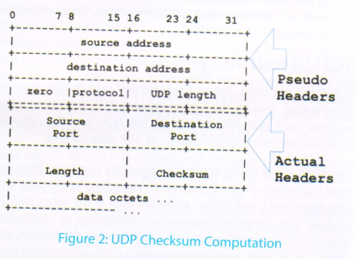
Even though UDP is unreliable, it still tries to ensure that it delivers uncorrupted data to the other end using a 16-bit checksum. The entire packet (including UDP headers, pseudo-headers – which includes source and destination IP addresses, protocol, and length field – as well as application data) is split into 16-bit words. The checksum is computed by adding all these 16-bit words, adding back the overflow/carry bit(s), if any, and then taking 1’s complement of the result.
Let us understand this calculation with an example. Figure 2 below provides the values of the various fields used in the checksum computation: the source IP address, the destination IP address, the protocol (the value for UDP is 0x11), the source port, the destination port, the length (twice: once in the pseudo header, and once in the UDP header), and the application data (16 bits at a time).
UDP uses pseudo-headers in computing checksum values to avoid misdirected deliveries i.e., packets delivered to a destination application different from the intended recipient application. To understand the role of pseudo-headers, consider a network setup as shown in Figure 3. Suppose an application on Hb sends a UDP message to Ha using only UDP headers and data (i.e., without using pseudo-headers to compute the checksum). Thus, the sender Hb will use only UDP source-port, destination-port, length and data values to compute the checksum. This packet is forwarded to Router R for further delivery. Let us assume that Router R has some bug, and while forwarding the packet from its input interface to its output interface, it erroneously modifies the destination address to that of Hc. (Such a bug is unlikely today, as router code has matured over last 30+ years that TCP/IP has been in existence.) After this modification, the packet is transmitted with its applicable IP layer checksum and link layer error checking. Since the IP layer and link layer checksums are computed after the change of IP address by the router, these checksums will pass and this packet will be (erroneously) delivered to Hc. If another application is running on Hc and is accepting the packets on the same port number which was used by the application on host Hb, this application will receive and process the misdirected packet. The checksum at Hc will pass successfully since it uses only source and destination port and data. Such a scenario is called misdirected delivery.
To avoid this scenario of misdirected delivery, pseudo-headers (involving IP address of source and destination nodes) are used in the UDP transport protocol checksum computation.
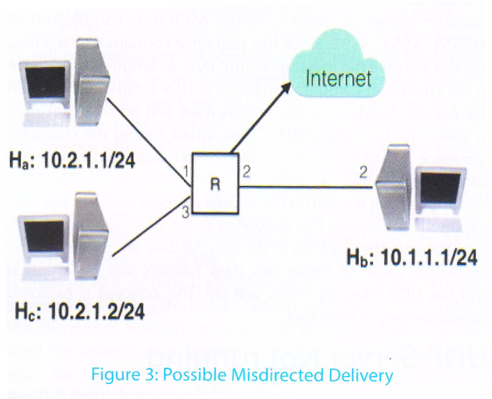
With pseudo-headers, when Hb sends a UDP packet to Ha, it computes the checksum using the application data, the source and destination ports, the packet length, the source IP (Hb) and the destination IP (Ha). This packet will be delivered to router R for further forwarding. This time, if R errs and once again modifies the destination address to Hc, the packet will be delivered to Hc as the error check at the IP and link layers will pass through. However, when Hc receives this packet, it will compute its own checksum using the application data, UDP headers, source IP of Ha and destination IP of Hc (and not that of Hb). This checksum value will (almost certainly) be different from the checksum received in the UDP header. In this case, Hc will discard the packet i.e., the packet will be lost but at least it will not be wrongly delivered to an application on an unintended host.
In addition to avoiding misdirected delivery, the UDP checksum performs a basic integrity check on application data. In case errors are detected, it discards such the packets. However, this integrity check is not foolproof, as the following example shows. Suppose the sender transmits the application data “Computer” (ASCII representation in 16-bit chunks: 0x436F 6D70 7574 6572) to the receiver and computes the checksum. For simplicity, let us ignore headers in the calculation of the checksum: 0x436F + 6D70 + 7574 + 6572 = 0x18BC5. After adding the overflow carry value ‘1’ back to restrict checksum value to 16 bits, the value becomes 0x8BC6. The 1’s complement of this value is 0x7439, which will be the checksum value.
A deeper examination of this checksum computation shows that if the value 0xFFFF is added to 0x18BC5, the new value will be 0x28BC4. When the overflow carry value ‘2’ is added to restrict the checksum to 16 bits, the value is 0x8BC6 – the same as before adding 0xFFFF. Naturally, the 1’s complement value is once again 0x7439. Thus, if one can find some character sequence that will add up to the value 0xFFFF, then these two messages will have same checksum values.
While working out on such a character sequence, one should take into account the ‘length’ field used in both UDP headers and pseudo-headers (Figure 2) [2]. For instance, consider the character sequence “UQUQUQ” whose ASCII code corresponds to 0x5551 5551 5551. Since this sequence contains 6 characters, this will increase the message length by 6. As length is used twice in the checksum computation (once in UDP header and once in the pseudo-header), so the length itself will add 12 (decimal) or 0x0C to the computation. Thus, when adding the character sequence “UQUQUQ”, the checksum computation involve an extra addition of 0x5551 + 5551 + 5551 + 0x0C = 0xFFFF. This implies that if a man in the middle attacker modifies the data packet by appending this sequence at the beginning of data or at the end, then as long as the original data length is even, the checksum value of these two data packets will be identical and the UDP integrity check will fail. This concept is explored experimentally in Exercise 3.
Consider the situation when the UDP Server application is down (e.g., crashed or not yet started) and the UDP Client application is unaware of this. When the UDP Client (sender) sends a message to the Server (receiver) application, these packets are discarded when received by the host because there is no receiver at the UDP layer listening on the destination port specified by the sender. However, the receiver host does inform the sender host of this non-delivery of the UDP packet. This error communication is sent using the ICMP (Internet Control Message Protocol) [5] error message “Port Not Reachable”. This error message is sent and received at the IP layer, and it will thus not be delivered to an application that is just using transport layer connectivity. To process such messages at the network layer, the application program should work with raw sockets (at the IP layer). Readers are encouraged to explore programming with raw sockets to enhance their understanding.
The experimental exercise to understand the behaviour of the Client (sender) application when the Server (receiver) application is not running is described in Exercise 7.
Since UDP does not provide any packet ordering and (almost) no information on packet loss, this protocol is useful for applications that primarily work in a query/response mode. The functionality of these applications should be tolerant to packet loss. Two key Internet applications that work with such requirements are Domain Name Service (DNS) [6] and Network Management. Both applications send a UDP request, and when they receive the response, they act upon it. In case a response is not received, the service is not provided. DNS requests are independent of each other, and hence no ordering is needed. For example, when a user opens two browser windows and enters www.google.com and www.yahoo.com the browser will send two independent DNS requests and process their responses accordingly. If one of the responses is received and the other is not, the browser will display the former web-page and will independently display an error for the latter page.
Applications that require continuous exchange of data packets in a specified order need to establish their own protocol to deal with packet loss and out-of-order delivery. A typical mechanism is to add the sequence number (or some sort of identification number) to each packet so that the receiver can process the received packets in the correct order. Further, the application must establish acknowledgement and timeout mechanisms so that the sender can retransmit the packets in case of packet loss and/or corruption. Implementing this timeout and retransmission of packets as well as sequence numbers of packets is a big overhead. To avoid burdening each application with this overhead, TCP provides reliable delivery of data. We now explore several concepts related to TCP.
TCP at the transport layer is implemented only in end systems. Intermediate routers do not implement TCP (for routers, the network stack is limited to just the link layer and the network layer) and are essentially unaware1 of TCP data packets.
Reliable delivery of TCP implies that it will try to recover from any error that occurs, either at the underlying network or at the transport layer, and it will deliver error-free data at the other end. As we have seen, errors in message communication can occur due to packet loss, packet corruption and/or packet duplication, etc. When TCP receives a corrupted packet (i.e., its own computation of the checksum is different from the checksum in the TCP header), it simply discards the packet and treats this packet at par with packet loss. The TCP sender waits for acknowledgement of the data it has sent. When it does not receive such an acknowledgement within a certain timeout period, it assumes that the packet is lost and it retransmits the packet. Each time, it retransmits the packet, it doubles the timeout value. This is because TCP assumes that packets are being lost due to congestion in the network. Thus, to ensure that retransmission does not add to existing congestion, it slows down the rate of packet transmission by doubling the timeout period. Since the network may still be facing congestion, retransmitted packets may also be lost. Successive retransmissions after doubling the timeout period go on for a number of times (as configured/implemented in the TCP stack). If none of the retransmitted packets are acknowledged, TCP finally assumes that network has encountered a major disturbance and breaks the connection. In such a situation, packet delivery naturally fails, and hence it is erroneous to believe that TCP can guarantee packet delivery. TCP reliability has to be understood in this context. TCP does, however, guarantee that if and when it succeeds in delivering data to the receiver application, the data will be delivered in-order, error-free and without any duplication. (There is no guarantee that all the data it has received from the sender will be delivered to the receiver.) TCP is also characterized as a streaming service, which implies that it treats the entire input data from the sender as a stream of bytes. In particular, it does not distinguish between different data segments given to it by the sender application. For example, if sender sends 100 bytes in first send request, 200 bytes in the second send request, and 250 bytes in the third send request, it treats all of this data as a single stream of 550 bytes. The receiver application at the other end would not know whether the sender had sent three segments as mentioned above, or a single data segment of 550 bytes, or 550 segments of 1 byte each, etc. For TCP, the entire data is treated as a stream of bytes and delivered as such at the receiving end. All that TCP guarantees is that the receiving application will receive these bytes in the order sent i.e. byte number N+1 will be given to application after byte number N, and before byte number N+2 for all values of N.
The TCP byte-streaming concept between two end points (applications) can be understood using the following analogy. Consider a water pipe connecting two containers CA and CB so that water can flow from CA to CB. Now, water can be poured in at CA one bottle at a time, or one bucket at a time, or one spoon at a time, etc. When the water comes out at CB’s end, the water pipe does not provide any information about how the water was poured in at CA’s side – it just arrives as a stream of water drops. Further, the water pipe does not guarantee that all the water poured in at CA will be delivered at CB (e.g., the pipe may break).
Now we will discuss this concept with the experimental exercise as below. Consider the setup as shown in Figure 1, and repeat the exercise as discussed in UDP Message Orientation. The Client program will send C distinct messages at an interval of D seconds, where the size of each message is X bytes. The first message consists of the letter ‘A’ repeated X times, the second message consists of the letter ‘B’ repeated X times, and so on. The Server program will read Y bytes on the TCP socket and display the same on the console. As an example, suppose X = 50 and Y = 30. When the Server invokes the first read, it will read 30 letters ‘A’. When it invokes the next read, it will get the remaining 20 letters ‘A’, because TCP is a streaming protocol and all bytes are delivered as a stream. On the next read, it will get 30 ‘B’s, and so on. If the server program is changed to use the value of Y = 5, then it will read 5 letters at a time. Its very first read request will read 5 letters ‘A’, the second read will get the next 5 letters ‘A’, and so on until the tenth read request will get the last 5 letters ‘A’. The next read will result in reading 5 letters ‘B’, and this will occur 9 more times, etc. A similar pattern can be observed when Y = 1. In all these three exercises, the Client (sender) program remains the same. This demonstrates that TCP is a streaming protocol and does not honour message boundaries of data sent by the Sender application.
The steps for experimental exercises to experience TCP streaming are detailed in Exercise 4.
In addition to providing streaming service for data delivery, TCP also provides reliable communication of data in the sense that if any packets are lost or corrupted in transit, TCP will take care to retransmit these so as to ensure that receiver receives this byte stream in-order and uncorrupted. To understand the TCP Reliable delivery, let us re-implement the exercise UDP Packet Loss using TCP. Suppose the Client application sends 10 TCP data packets (segments) at an interval of 5 seconds between successive transmissions, starting at time T0. Thus, the tenth data packet will be transmitted at time T0+45. Now suppose we break the link between switches S1 and S2 at time T0+16 (say), and we restore this link at time T0+32 (say). At time T0+20, when the Client sends the fifth packet, it will be dropped at switch S1 since there is no link to S2. Thus, this packet will not reach server Hs. Hence, client Hc will not receive any acknowledgement and, after the timeout (which is likely to be few milliseconds since the earlier deliveries and acknowledgements would have completed in a few in a LAN setup), the Sender client will retransmit the packet and double the timeout value. When the acknowledgement for the retransmitted packet also does not come, the Client will retransmit again with double the timeout for acknowledgement. The tool tcpdump or wireshark can be used (at the at Sender side) to verify these retransmissions at increased (doubled) intervals. All this retransmission occurs at the TCP layer, and the Client application is unaware of it. At time T0+25, the Client will send the sixth data segment containing the letter ‘F’, which will lie in the TCP buffer at the Client host. Similarly, at time T0+30, the Client application will send the seventh data segment containing letters ‘G’, which will again be stored in the TCP connection buffer. Depending upon the TCP flow control window size, this data segment may also be transmitted along with the previous data during the next retransmission. When the next data retransmission takes place after time T0+32 (i.e., after the link is restored), the Server (receiver) will receive all the data segments (fifth to seventh), and it will send acknowledgements for all data segments received so far. TCP follows cumulative acknowledgement, thus the acknowledgement from the receiver will be for the seventh segment, which also implies that the fifth and sixth segments have been received. With this acknowledgement, the TCP timeout value will be reset to the response time delay of the retransmitted packet, and subsequent TCP data segments will be transmitted as data segments one to four were.
Analysis of the Server side behavior will show that it receives the data segment containing ‘A’s at time T0, ‘B’s at T0+5, ‘C’s at T0+10, and ‘D’ at T0+15. During the time window from T0+16 to T0+32, no data is received. At time T0+32, it receives ‘E’s, ‘F’s and ‘G’s, all together (in order), and these are displayed on the Server application terminal. An analysis of tcpdump/wireshark capture can be used to analyze these packets to demonstrate how TCP implements reliable delivery on packet loss. The tcpdump/wireshark capture at the Client side shows multiple retransmissions, but at the Server side there will be only one segment received after time T0+32.
The experimental steps to understand packet loss and TCP recovery from packet loss are described in Exercise 5.
To develop a comprehensive understanding of TCP protocol basics, we also need to study what happens when the Server program crashes during communication, or when the Server application is not running when the Client starts communication. In all such cases, when the Server host receives a TCP packet for a destination port number and no application is ready to receive this data by binding to this port and listening on it, the TCP stack generates a TCP Reset response. The TCP Reset is indicated by TCP flag bit ‘R’ in the TCP header. When the sender of the communication receives the TCP Reset bit with value 1, the TCP stack implementation at sender host simply closes the connection, and the sender application receives an error (system call error) when it makes use of the associated socket.
The set of steps to understand TCP Reset are described in Exercise 6.
We have explored the basic working of transport layer protocols TCP and UDP in the TCP/IP stack. The key features of both these protocols are discussed. We have developed hands-on exercises to enhance understanding of UDP (with its unreliable delivery that nevertheless honours message boundaries) and TCP (to demonstrate how it provides streaming service, reliability of data transmission using retransmission and timeouts, and in-order delivery). We also experimentally investigated the behaviour of both UDP and TCP when a Client application initiates a connection to a non-running Server program. These experimental exercises with detailed steps will help the reader assimilate these concepts clearly, and will develop a deeper understanding of these two transport layer protocols.
In the next article, we will discuss the TCP state transition diagram, and how TCP connections move from one state to another. The understanding of TCP connection states will be very useful for Information Technology professionals to diagnose and debug application connectivity when web applications behave unexpectedly.
1.If intermediate devices implement Network Address Translation, then these devices may need to look up TCP port numbers.
All the example programs as described in these exercises can be downloaded from [8]. To carry out these experimental exercises, four simple Python programs are used which are listed below and accessible at [8].
i. udp_client.py
ii. udp_server.py
iii. tcp_client.py
iv. tcp_server.py
One does not need to understand Python in detail to use these programs. Python is very readable, and even a cursory reading of these programs will provide insight into their functionality. If these programs are downloaded on a Linux (e.g., Ubuntu) machine, give them execute permissions in the terminal window (i.e., chmod +x *.py) so that they can be invoked directly as ./udp_client.py, etc. Use the option -h to understand the usage syntax (e.g., ./udp_client.py –h). By default, both the TCP and UDP server programs listen on port number 9999 the use the IP addresses that have been assigned to the server host. The server program reads the data in the buffer size of 20 bytes (default value) and reads data from socket without any delay and displays the same. The client program by default connects to the server on port 9999, but requires the server’s IP address to be specified as a command line argument with the -s option. The client uses a buffer size of 50 bytes (default value) and sends 10 messages (default) at interval of 5 seconds (default) each. All these values are configurable and can be changed when running the program to enable experimentation with various permutations and combinations. The options for these programs are:

All the exercises use the network setup as shown in Figure 1. The programs are invoked in the terminal command windows.
Note: When using Wireshark capture on the client, use the capture filter as “host 10.1.1.1” (where 10.1.1.1 is server’s IP address – replace this value as per your experimental setup). Similarly, when running Wireshark capture on the server host, use the capture filter as “host 10.1.1.3” where 10.1.1.3 is the IP address of the client machine.
a. Run the UDP server program on server host Hs (./udp_server.py).
b. Run the UDP Client program on client host Hc (./udp_client.py). This will start sending message of 50 bytes size, 1st message containing letter ‘A’, 2nd message containing all ‘B’s, and so on. The client program also displays the data that is being sent.
c. Study the data displayed on server application terminal command window. It will display 20 letters of ‘A’ immediately after client program is invoked, and then the after the lapse of client delay time will display 20 letters of ‘B’, and so on.
d. Even though client has sent 50 number of ‘A’ (data), the server application has received only 20 and displays only 20 bytes of message. This demonstrates message oriented service delivery of UDP protocol.
e. Run the Wireshark capture on server and analyze the actual amount of data received. It will be equal to what client has sent.
f. Rerun the client and server programs with different buffer size, number of counts etc. and analyze UDP behavior.
Note: For, both the client and server program, use the buffer size more than 1500 bytes and analyze Wireshark capture to see the UDP message being fragmented at the IP layer. Observe that UDP will continue to deliver the entire message in one go to the application.
a. Repeat the above exercise (Exercise 1) with client sending 10 messages at intervals of 5 seconds.
b. Server should display first message as ‘A’, and so on.
c. Break the link between switch S1 and S2 at 16th seconds and restore this link at 32nd second. To break
the link, just remove the Ethernet wire connecting 2 switches.
d. Analyze the server response displayed on the screen. It should display first 4 messages at interval of 5s,
and then there should not be any display for next 20 seconds i.e. it should not display any message from
5th to 7th and then it should display 8th, 9th and 10th message again at the interval of 5s.
e. Using wireshark, analyze the packet sent by client as well as those received by server. Identify which
packets are received and which are lost. The capture at client should show transmission of all the 10
packets, but capture at server should show 7 packets received implying 3 packets are lost.
f. The program demonstrates the unreliability of UDP protocol and that any lost packets are not retransmitted by UDP protocol.
a. To understand UDP checksum i.e. Integrity check and be able to modify the data, we will use nc tool for both client and server.
b. On the server machine, in the terminal window, run ‘nc –u –l 8192’. This will run UDP server on port number 8192.
c. On the client machine, in the terminal window, run ‘nc –u 10.1.1.1 8192’, where 10.1.1.1 is the server’s IP address. Use the appropriate IP address as applicable in your experimental setup.
d. Run wireshark capture on client and/or server machine.
e. Enter some text e.g. “Hello” (and press enter to send) on client machine where nc is running. Server nc window should show this text message. Note down the UDP Checksum value in the wireshark capture. It is the 4th and last field in UDP header.
f. On the client terminal running ‘nc’, now enter “UQUQUQHello” and send it to server.
g. Analyze the UDP Checksum for this message sent to server. This should have same checksum value as
corresponding to “Hello”.
h. On the client terminal, enter “llHeo” and send the message.
i. The wireshark capture should still show the same checksum value.
j. This exercise demonstrates that UDP checksum works at a very basic level and any new message can be
constructed to have the same checksum.
Exercise 4
Topic: TCP Streaming
a. Repeat the exercise for UDP message boundary (Exercise 1:) but with TCP Client and TCP server instead of UDP. The client should send 10 messages, each message of 50 bytes, at intervals of 5 seconds
b. The TCP Client program should read 20 bytes of data from the socket at a time (use the option –b 20 indicating buffer size of 20).
c. The server should display the message in chunks of 20bytes (or 10 bytes) but will display the full message content (though in parts) unlike the UDP case where only first 20 bytes are displayed.
d. Server should display all the 10 messages in the same order as sent by the client.
e. Analyze the TCP message transmission using wireshark on client and server.
f. Rerun the server program with buffer size of 5 bytes, and delay of 1s and verify that server still receives
all the messages though messages will be displayed in chunks of 5 bytes at every 1s. Still no message should be lost.
g. Analyze this above behavior using wireshark at what times messages were transmitted and what time
these were received. The message may be received much earlier but display of these message chunks could be much later on account delay introduced in server program.
h. Next, repeat this exercise but this time server program should read 100 bytes at an interval of 10s (by
default it is zero).
i. In two second interval, two message will arrive from the client and thus server should receive all the 100
bytes in one read call i.e. TCP combines the data of two different segments when such data is available.
j. This program demonstrates that TCP provides streaming service for data delivery.
a. Repeat the above exercise for TCP streaming (Exercise 4:) The TCP client should send 10 messages, each
message of 50 bytes, at intervals of 5 seconds
b. Server should display first message as ‘A’, in the chunks of 20 bytes and so on.
c. Break the link between switch S1 and S2 at 16th seconds and restore this link at 32nd second as before.
d. Analyze the server response displayed on the screen. It should display first 4 messages at interval of 5s,
and then there should not be any display for next 20 seconds. After 32nd second, it should display contents of 5th to 7th message immediately one after the other, and then it should display 8th, 9th and 10th message at the interval of 5s. The messages from 5th to 7th are stored in TCP buffer in client side and would be repeatedly retransmitted at double the time interval (TCP timeout) from its previous transmission.
e. Using wireshark, analyze the packet sent by client as well as those received by server. Analyze how many
TCP Segments are retransmitted. Especially, analyze when the 5th, 6th and 7th message do get transmitted.
f. Analyze at the server, which TCP segment contains the message from 6th to 7th. All of these should be
received by the server in the single segment rather than separately.
g. In the packet capture analyze the time when TCP segments are retransmitted. This time gap should
keep on doubling at each retransmission till an acknowledgement is received and then transmission time
should be restored back to normal.
h. Analyze the acknowledgement of 6th and 7th message. There should be a single acknowledgement
rather than two separate. This indicates that TCP provides cumulative acknowledgement.
i. This exercise demonstrates use of TCP timeout and retransmission to provide reliable delivery of data.
Further, all the data bytes are delivered in-order at the server application implying that TCP always delivers data in order.
a. Repeat the exercise as carried out for UDP integrity check (Exercise 3:) but using TCP protocol. To use nc
with TCP, do not use the option ‘-u’.
b. Run the wireshark capture on client machine.
c. Do not run the nc server but just run the nc client and connecting to nc server i.e. on client terminal“nc 10.1.1.1. 8888”.
d. The wireshark capture should show that client initiating the TCP Connection by sending the TCP SYN
packet but it should receive TCP Reset packet in response since no server is running on port 8888.
e. Repeat the TCP streaming exercise as described about (Exercise 4:).
f. Start the wireshark capture on both client and server.
g. Once the first message is received on the server and it displays the content of first message, about the
server program. Press Ctrl-C on terminal windows running TCP server program.
h. Analyze the wireshark capture of TCP communication on both server and client. It should show
transmission of TCP Reset.
i. On receipt of TCP Reset, the client socket will be closed by TCP stack on client side and any further usage
will result in about of client program as well.
a.Repeat the exercise as carried out for UDP integrity check (Exercise 3:) but do not run the UDP Server.
b.Run the wireshark capture on client machine.
c.Just start the UDP client using nc and send some data.
d.Analyze the wireshark capture on client. It should show ICMP Error “Port Unreachable”.
e.This exercise demonstrates UDP communication behavior when no application is running to receive the UDP message.
[1] RFC 793, “Transmission Control Protocol“, Information Sciences Institute, USC, CA, Sep 1981, https://tools.ietf.org/html/rfc793. Last accessed Aug 2018.
[2] RFC 768, “User Datagram Protocol”, J. Postel, Aug 1980, https://tools.ietf.org/html/rfc768, last accessed Aug 2018.
[3] RFC 791, “Internet Protocol”, Information Sciences Institute, USC, CA, Sep 1981, https://tools.ietf.org/html/rfc791, last accessed Aug 2018
[4] RFC 2616, “Hyper Text Transfer Protocol – HTTP/1.1”, Network Working Group; Fielding, Gettys et al. June 1999, https://tools.ietf.org/html/rfc2616, last accessed Aug 2018
[5] RFC 792, “Internet Control Message Protocol”, Postel, ISIS, Sep 1981; https://tools.ietf.org/html/rfc792, last accessed Aug 2018.
[6] RFC 1035, “Domain Names – Implementation and Specifications”, Mockapetris, ISI, Nov 1987; https://tools.ietf.org/html/rfc1035, last accessed Aug 2018.
[7] Netcat (nc) command utility, http://manpages.ubuntu.com/manpages/xenial/man1/nc.traditional.1.html, last accessed Aug 14, 2018.
[8] Source code and example access on github. https://github.com/rprustagi/EL-Basics-of-Transport-Layer/tree/master Last accessed on Aug 16, 2018.
[9] Wiireshark – The Network Protocol Analyzer, https://www.wireshark.org/#learnWS, Last Accessed Aug 2018.