
In the previous article [1], we have studied assignment of IP address [2] to a host, and its role in connecting to internet and communicating with other devices. We explored concept of a network number which is determined using IP address and subnet mask. When network number of two hosts is same, then these two hosts belong to same network else these hosts belong to different networks. Hosts within the same network communicate directly with each other whereas hosts belonging to different network communicate using one or more intermediate routers. A router connects two networks, and its main job is to receive packets from one network and forward it to another network so as to enable the packet delivery towards its final destination. When two hosts are connected by many intermediate networks, communication between these two hosts requires that each of the intermediate routers in the path forward the packet on to the network which is closer to the destination and router in the last leg of this path will deliver the packet to destination host. In this article, we will explore this concept of packet forwarding and the mechanisms used to achieve this packet forwarding.
Consider the connectivity of two networks, say Network-1 and Network-2, as shown in Figure 1. Each of these two networks consists of many connected systems (though as a representation only 2 are shown). Hosts H1 and H2 are part of Network-1, and hosts H3 and H4 are part of Network-2. These two networks are connected via many intermediate routers, which we can consider as representing the internet. Hosts H1 and H2 belongs to same network 10.x.x.0/24, and hence can communicate directly without requiring any intermediate router. Similarly, host H3 communicates directly with H4 as both belong to same network 10.y.y.0/24. However, when H1 needs to communicate with H3, the packets have to go through all the intermediate routers. When H1 wants to send a packet to H3, it will forward the packet to router R1, which in turn will forward the packet to next router R2, and so on, and finally Router Rn will deliver the packet to host H3. Thus, communication between two hosts involves routing of packets and primary focus of this article is to explore the mechanism used in forwarding these packets.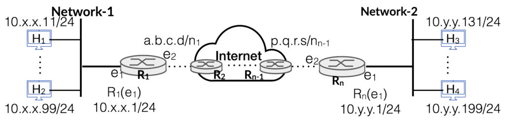
Figure 1: Connectivity of two Networks, each network having many systems in it
Whenever, a host needs to send a packet to other hosts, it must know the IP address of destination host. For example, when we use browser to search at google.com, the machine where browser is running, finds the IP address of google.com and then sets up TCP connection using IP address of google.com. When sending a packet, a host consults its routing table (also called as forwarding table) and determine the next hop in the path to destination host. Entries in the routing table play a crucial role in how a host makes a packet forwarding decision. The routing decision using the routing table is always required irrespective of whether the destination host is in the same network or a different network.
The main purpose of routing table is to help a host in determining the next hop where packet should be forwarded. The next hop could even be the next intermediate router or the final destination host itself. At its core, routing table has following four column fields, though in many implementations it may have some more information fields, such as cost metric etc., which we will not consider for our discussion.
A routing table would have number of row entries, with each row corresponding to a destination network. First two fields together identify a network, and are used to check if destination IP address of packet belongs to this network. If this entry matches, then packet is forwarded on the associated interface (3rd field) to the next hop (4th field). Next hop entry field is applicable when destination host is not connected to local network and identifies the IP address of next router in the forward path. A typical set of entries for router R1 in Figure. 1 is given below in Table 1, and routing entries for host H1 is given in Table 2
Table 1: Routing entries for R1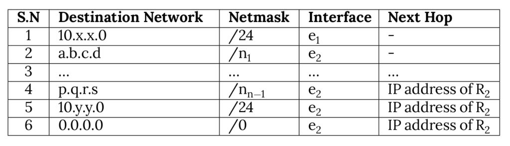
Table 2: Routing entries for Host H1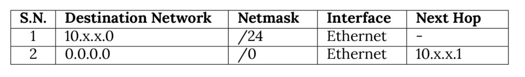
First two entries in Table 1 correspond to two networks to which router R1 is directly connected and hence there is no next hop address. These will be followed by number of entries corresponding to network numbers that exist in the network. The entries in 4th and 5th rows correspond to two networks connected with the router Rn. Lastly, there is an entry corresponding to 0.0.0.0/0 which is also referred to as default route entry. Use of this default entry is explained ahead. For any host which is typically connected to a single network, there are generally two entries, as shown in Table 2 for host H1. One entry corresponds to local network and other entry corresponds to default network i.e. 0.0.0.0/0. These entries are sorted in the decreasing order of number of bits in netmask. For example, entry for netmask /27 will come before entries of netmask /26 or /25 etc.