
So far in our articles [1], we have discussed a) Internet and network in general, such as, its functioning, network delays and performance, diagnostic tools to use etc. b) Application layer with detailed focus on HTTP protocol, its message structure, and use of HTTP headers in designing web applications, and c) Transport layer with focus on end to end delivery i.e. delivery of data from a process on one machine to a process on another machine. At the core, all of these require network communication between two computer systems. In this article, we will explore basics of communication mechanisms at network layer i.e. data exchange between two computers systems.
When Internet started, Internet designers initially fixed the size of Internet address as 32 bits. This limits the maximum number of possible addresses to 232 (about 4 billion). At that time, no one had imagined and expected Internet to grow to a size as it has reached today. This current address format is also known as IPv4 address. Initially, network layer was part of transport layer and it was separated from transport layer in early 80s. Till that time TCP [4] had already undergone 3 revisions and thus when IP [3] was separated from TCP, it was christened IPv4. Subsequently, after the invention of web in early 90s, Internet started to grow at a fast rate and in few years, thus very soon number of devices connected to Internet would have exceeded 4 billion. Thus, a new Internet addressing scheme, called IPv6 [8], was designed with the primary objective of connecting large number of devices. In IPv6 address space size is fixed at 128 bits. With these many bits, total number of addresses would be 2128. Considering the world population to be around 8 billion, the number of addresses per person would come to 295, a very high number. This address space is so large that even if each conceivable entity on this earth is assigned an IPv6 address, we would still have a large number of addresses available. We will explore IPv6 in subsequent articles.
A computer system can communicate with other computers only when it is connected to a network via some network interface. A machine can have many network interfaces and thus can connect to many networks at the same time. Examples of multiple such interfaces are Wired ethernet, Wi-Fi, Bluetooth etc. When a machine is connected on multiple interfaces, a common question that arises is: does it have a single network address or multiple addresses. This can be better understood by an example analogy. Consider a 3-side corner building i.e. it is spanned on its sides by 3 roads. Consider that it is situated on 5th main on west side and spanned by 3rd cross on north and 4th cross on south side (we assume that on the east side, it has another neighbouring building). Let us further consider that the municipality when assigning the building numbers on each road has assigned it #100 on 5th main, #200 on 3rd cross and #300 on 4th cross. Thus, building can be reached by using any of these 3 addresses, that is, #100 5th main, or #200 3rd cross, or #300 4th cross. Thus, all three addresses belong to same building, though in reality, these addresses correspond to entry doors on the roads spanning the building. By analogy, the entry door of the building on a road acts like a network interface of a computer, and road can be considered as network link. Thus, network address in true sense is assigned to the network interface and not to the machine. When a machine has only one active network interface, network address is commonly attributed to address of machine as well and the two are interchangeably used in general.
The network interface of the machine enables it to connect to a network. As the network address is of fixed size (32 bits for IPv4), one has to identify the network as well as unique address within the network from this network address itself. Thus, network address is divided into two parts: network part and host part. It is similar to door address of the building like door number (Host part), and road name (Network part). When two buildings have same road name in their addresses, these are considered part of same locality. Persons in these two buildings on the same road can reach each other without ever going through a road crossing. Similarly, two computer systems can communicate directly with each other when both belong to same network i.e. have same value in network part of the address. If for two computers, the value in network part differs, then these systems belong to two different networks, and thus, can’t communicate directly. Systems connected to different networks can communicate only when these networks are connected by intermediary devices, known as routers. The size of network portion (number of bits starting from most significant bit) decides how many machines can belong to that network (by analogy, length of the road determines number of buildings that can exist on that road).
During the early days, networks were envisaged to belong to three categories: a) Large networks, b) Medium size networks, and c) Small size networks. These three networks were correspondingly classified as Class A, Class B and Class C networks [2], and respective number of bits in the network part of the address were fixed to distinguish between these classes. First 8 bits were assigned for class A; first 16 bits were assigned for class B, and for class C networks first 24 bits were assigned. The classification is depicted in Figure 1. Two more classes were defined as well, namely class D and class E. Class D is used for multicast addresses and have first 4 bits as 1110. Class E is reserved for future use, even today it continues to remain reserved.
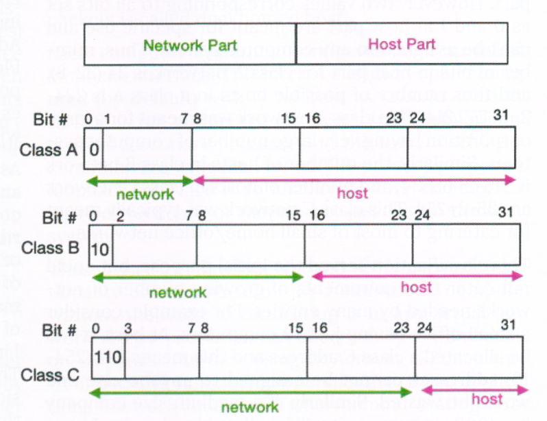
Figure 1: Initial classification of IP addresses
Since these first few bits are overlapping among these 3 classes, these classes are identified by setting specific value for initial few bits in network part. Class A network has its first bit set as 0, and the value 01111111 of first 8 bits in the network part is reserved for local loopback interface. Thus, total possible number of values for class A network would range from 00000001 to 01111110, a total of 126 (=28-2) values. Similarly, class B network is identified with value of first two bits as 10. Thus, total number of possible class B networks are 214=16392 (first 16 bits would range from 10000000 00000000 to 10111111 11111111). Class C network is identified with first 3 bits as 110, and thus have 221 possible values for network addresses. For any of these 3 network classes, there is no classification in the host part. However, two values corresponding to all bits set as 0 and 1 in host part are meant for specific use and can’t be assigned to any computer system. Thus, number of bits in host part for class A network is 24 (32-8), and thus number of possible hosts in a class A is 224-2=1,67,77,214. This class A network was meant for a large corporation having very large number of computer systems. Similarly, the number of hosts in class B network is 216-2=65534, and number of hosts in class C network are 28-2=254. This class C network was typically meant for catering to most of small home/office networks.
This classification served the initial purpose, but could not cater to requirements of growing number of networks needed by many entities. For example, consider a small office having just 10 computers. At best, it will be allocated a class C address and this means 244 (254-10) addresses cannot be assigned to anyone else and would be wasted. Similarly, if a medium size company has 1000 computers, it will be allotted a class B address which again will result in non-usage of 64534 (65534-1000) addresses. Thus, this fixed classification resulted in under-utilization or wastage of network addresses. Considering this wastage, this classification with fixed size of network was done away with and instead varying size of network part was introduced. This is described in details in RFC 4632 [10]. A network needs to have a minimum of two computers for them to communicate, and hence, host part should provide for at least 2 addresses. Since for any network, 2 more values need to be used (all 0s and all 1s), thus we need a total of 4 values in host part i.e. 2 bits. Thus, network portion can have maximum of 30 (=32-2) bit. Thus, for all practical purposes, netmask can be maximum /30. Similarly, the network portion can have minimum of 1 bit, though most unlikely to be used as it would leave 31 bits for host part implying 231-2 systems in a single network (a hypothetical case).
Representing IPv4 address in binary form with 32 bits is cumbersome to read and understand. Representing it as an integer value would be a shorter form but difficult to differentiate between the network and host part. For an easy understanding and interpretation, 32 bits are divided into 4 octets (8 bits) and these are written using decimal value separated by ‘.’ (Dot). Though there is no formal specification for this representation, these were first time described in RFC 790 [2]. The IP address is written as a.b.c.d/n, where a, b, c, d correspond to decimal value of each octet and n represents the number of bits in the network part. Typically, any computer system or a smartphone connected to a Wi-Fi hotspot will have its IP address as 192.168.x.y/24 (x value would range between 0 and 255, and y value would range between 1 and 254), implying that network portion is 24 bits. Similarly, another IP Address in the same network would be 192.168.x.z/24. Please note that /24 is used to identify the network portion of the IP Address. Thus, these two IP addresses 192.168.x.y and 192.168.x.z belongs to same network with /24 as netmask (24 bits of network portion).
As each system connected to a network need to have an IP address (more precise would be the IP address of connected interface), as a first step towards our experiential learning, we would like to find the IP address of the computer one uses in day to day life. IP address of a Linux system can be identified by using the command ‘ip address show’ on the command terminal of the system as shown in Table 1. In older versions of Linux, the command ‘ifconfig’ was generally used. This old command is still supported in current versions but has been deprecated and it is recommended that user should avoid using this ifconfig command. Similarly, to find IP address of Android phone (when connected to a hotspot), typical set of steps would be Settings → About → Status, and it will display IP address and other information related to the Android phone. For a Windows system, one needs to explore its settings via Network → interface → properties → TCP/IP address. The set of steps for experiential exercise to know the IP address of a system is given in Exercise 1.
Table 1: Finding IP address of a Linux machine
$ ip addr show 1: lo: <LOOPBACK,UP,LOWER_UP> mtu 65536 qdisc noqueue state UNKNOWN group default qlen 1000 link/loopback 00:00:00:00:00:00 brd 00:00:00:00:00:00 inet 127.0.0.1/8 scope host lo valid_lft forever preferred_lft forever inet6 ::1/128 scope host valid_lft forever preferred_lft forever 2: enp0s5: <BROADCAST,MULTICAST,UP,LOWER_UP> mtu 1500 qdisc fq_codel state UP group default qlen 1000 link/ether 00:1c:42:5a:62:92 brd ff:ff:ff:ff:ff:ff inet 10.211.55.11/24 brd 10.211.55.255 scope global dynamic noprefixroute enp0s5 valid_lft 1065sec preferred_lft 1065sec inet6 fdb2:2c26:f4e4:0:9091:5823:b5b0:ee69/64 scope global temporary dynamic valid_lft 604072sec preferred_lft 85669sec inet6 fdb2:2c26:f4e4:0:4ba2:dc6c:c082:b421/64 scope global dynamic mngtmpaddr noprefixroute valid_lft 2591700sec preferred_lft 604500sec inet6 fe80::2d45:435:36ec:a36/64 scope link noprefixroute valid_lft forever preferred_lft forever |
Table 1 shows two network interfaces, namely as lo and enp0s5 for a Linux system along with their IP addresses. The first interface lo (or lo0 on few other machines) corresponds to loopback interface. The second interface enp0s5 corresponds to actual network interface which connects this system to the ethernet network with its address as 10.211.55.11/24. The interface name may vary depending upon the variant and version of the Linux e.g. it could be eth0 or wlan0 (for Wi-Fi interface) etc. The representation /n (e.g. /24) for netmask represents number of bits in network portion. Role of netmask is to determine the network number (corresponding to the network portion) of the network address. If a system has multiple physical network interfaces, then each would have its own IP address but these would belong to a different network number. However, for most practical purposes, any end user system running a network application would have only one active network interface. An end user device either generates data packets and transmits these on to the network or receives packets on network interface and consumes the same. The devices that have two or more active network interfaces generally work as routers (or gateways) and their main function is to receive data packet on one interface and transmit it on to another interface depending upon the destination of the data packet. A computer system that has two network interface does not forward the packets from one interface to another, and only works as either producer or consumer of packets is called dual homed host.
Each computer system is configured with an inbuilt loopback interface. This interface is always pre-configured (by default) with IP address as 127.0.0.1. This interface is not connected to any external network and enables 2 or more processes on the same machine to communicate with each other. The primary purpose of loopback interface is to enable network communication between two or more processes within the same system. Thus, a user can develop, test and verify network functionality of an application on a standalone computer without the need of connecting it to any actual network. If two processes can successfully communicate on loopback interface using IP Address 127.0.0.1, then from network functionality perspective, these applications will work equally well when communicating on an actual network interface e.g. ethernet, Wi-Fi etc.
A netmask is used to compute the network number given the network address. This is computed by applying bitwise AND operation between 32 bits representation of IP address and netmask. Thus, first we need to convert /n netmask notation into 32 bits. The 32-bit representation of netmask /n is obtained by setting the value 1 for first n most significant bits and remaining 32-n bits as 0 and writing the entire value in binary (or DDN for better readability). Thus, netmask of /24 in binary form is written as 11111111 11111111 11111111 000000 which in DDN form would be 255.255.255.0. Similarly, netmask of /8 and /16 in DDN form would be respectively written as 255.0.0.0 and 255.255.0.0. These mask values of /8, /16 or /24 were simple to convert, as the boundary between all 1s and all 0s coincided with octet boundaries. For the netmask other than these values e.g. /21 would correspond to first 21 bits as 1, and remaining 11 (=32-21) bits as 0, that is, 11111111 11111111 11111000 00000000, which in DDN form would correspond to 255.255.248.0.
The computation of network can be better understood with an example. Consider an IP address IP1 as 192.168.43.11/21. The binary representation of IP address is 11000000 10101000 00101011 00010011, and binary representation of netmask is 11111111 11111111 11111000 00000000. Bitwise AND of these two gives 11000000 10101000 00101000 00000000 which in DDN form would be N1=192.168.40.0. Thus, network number of 192.168.43.11/21 is 192.168.40.0. In simplistic terms, we can also obtain the network number of an IP address by just setting all the bits in host part as 0. To help understand it further, consider two more network addresses IP2=192.168.42.24/21 and IP3=192.168.48.31/21, both having same netmask of /21. It has been author’s experience that on cursory look, some users think that all these 3 addresses belong to same network, which is not the case. Computing network number of the latter two IP addresses by applying bit wise AND operation, their respective network number would be N2=192.168.40.0 and N3=192.168.48.0. Since N1 and N2 are equal, this implies that addresses IP1 and IP2 belong to same network. However, N1 is different from N3, and this implies that IP1 and IP2 belong to different networks and systems belonging to these network can’t communicate directly and would require intermediate router(s).
Having computed network number, next natural question would be to determine number of possible addresses that can exist (or assigned to systems) in a network. This is solely determined by number of bits in the host part. We have just noted that in the host part, setting all bits as 0 gives the network number. Similarly, a network address achieved by setting all bits as 1 in host part is known as broadcast address. A broadcast address means all machines in the network. So, when a packet is sent to a broadcast address, then that packet will be delivered to all the machines in the network. It is needless to say that only live systems in the network will receive this packet, and any machine which is down will not receive this broadcast packet (there is no queuing of packets for later delivery). For example, broadcast address for 192.168.3.2/24 would be 192.168.3.255 (obtained by setting all the 8 bits of host part as 1). Similarly, broadcast address for network 192.168.40.0/21 would be 192.168.47.255. Thus, if a lab has network number as 192.168.3.0 and broadcast address as 192.168.3.255, then ping to the address 192.168.3.255 from a system would send the ping request to all the systems in the lab and receive response from all those systems which are up and running (Windows systems in the network would not respond as Windows have firewall enabled by default and reject any unsolicited incoming packet) . Thus, a single ping request to a broadcast address would result in receiving multiple responses. Exercise 3 provides the steps to send a broadcast ping request and receive multiple responses.
As netmask defines number of bits in network part, and thus number of bits in host part becomes 32-n. Thus, number of possible IP addresses that can be assigned to hosts in a given network with netmask /n will be equal to 232-n-2. The total possible values with 32-n bits are 232-n, out of which two values (corresponding to all 0s identifies the network number, and other corresponding to all 1s identifies broadcast address) are reserved, hence number of assignable IP address becomes 232-n-2. This computation serves as a basis to determine the number of bits required in netmask for an office network. Consider that an office has 20 computers and would like to get a network number so as to assign IP addresses to these computers in the office. For any network, we need to increase the count of IP addresses by 2 to account for network number and broadcast address, thus increasing the total address count in this office to 22 (=20+2). The minimum number of bits required to represent 22 values are 5. Thus, the number of bits in host part would be 5, and hence number of bits in netmask would be 32-5=27. Netmask of 27 bits enables 232-27-2=25-2=30 computers in the network. Even though the office needs only 20 addresses, the network will have 10 extra addresses which can be used in future (or may remain unused). This netmask of /27 is much better than assigning a class C address with netmask of /24 where it will only use 20 addresses and leave 254-20=234 address unused, and even in future office is unlikely to use them fully and hence assignment of class C address leads to wastage of network address space. Assuming the network number assigned to this network is 192.168.1.0/27 (11000000 10101000 00000001 00000000), then first assignable address in the network would be 192.168.1.1, the last assignable address would be 192.168.1.30, and broadcast address would be 192.168.1.31 (corresponding to all 5 bits in host part set to 1, i.e. 11000000 10101000 00000001 00011111). Please note that last octet of last assignable address is 30 and not 254. Quite often, author has seen that students err in computing the value of last assignable address, and mistakenly assume that the last octet of last assignable address is 254.
Typically, when a computer is connected to a network e.g. office LAN, or home Wi-Fi network, it gets an IP Address, and same is used by the computer for any communication with any other system. One question that naturally arises is: how does a computer gets the IP Address? Typically, each computer is generally configured as a DHCP (Dynamic Host Configuration Protocol) [7] client, and whenever a computer starts, it broadcasts a DHCP Discover message to check if there is a DHCP server present in the connected network. Typically, a Wi-Fi hotspot (or Internet/LAN router) acts as DHCP server in the network and responds to DHCP Discover request message. Similarly, in an office network where computers are connected via ethernet cables, and switches, there is a DHCP server configured by the network admin. The DHCP client initiates communication with DHCP server and obtains the IP address which it can use for the allotted time duration (known as lease time in DHCP parlance). On expiry of lease time, DHCP client renews this allotted IP address. On renewal, DHCP server is expected to allot same IP address as assigned before, but it is not guaranteed and DHCP server allots a new IP address which is different from the previous one. Further, It is the responsibility of DHCP sever to ensure that each system in the network gets a unique IP address, otherwise there would be a conflict, and machines with duplicate IP Addresses would not be able to communicate with any other system. As all systems have same network number, these systems in an office (or lab) can reach each other directly i.e. without requiring any router.
For a computer system, even though one IP Address is good enough to communicate with other systems, network layer specifications do not impose any restrictions on assigning multiple IP addresses to an interface. Assigning of multiple IP addresses to an interface becomes the necessity under certain situations. For example, during the time of current Covid pandemic, a good number of people are working from home and connect to their office/corporate network using VPN (Virtual Private Network) [9]. Now, network interface works with two IP address, one corresponding to IP Address as belonging to local network (e.g. Wi-Fi hotspot, or local home network) as assigned by DHCP server, and other corresponding to network that belongs to office facilitated by VPN server. We will use this concept of assigning multiple IP addresses to an interface, and assign an IP address of a different network to differentiate between reachability within same network and non-reachability to a different network.
Consider the case of network setup (e.g. in home or office) where two computers are connected to a network. For simplicity, let us assume that two systems CA and CB are connected to a Mo-Fi (mobile phone based Wi-Fi hotspot) and their respective IP addresses are 192.168.43.201 and 192.168.43.202 with a netmask of /24 (it is a typical example of IP address assignment when using Android phone as hotspot). The network number of these system would be 102.68.43.0/24. Ping to CB (IP address 192.168.43.202) from CA (having IP address 192.168.43.201) will be successful assuming no firewall in the network (or hotspot) blocking the packets in the network. Pinging an un assigned IP address in the same network e.g. 192.168.43.99 will result in no response and it will fail with timeout error. However, when we ping to an IP address in an unknown network e.g. 192.168.44.99 (with number as 192.168.44.0/24), generally, it may give an error indicating network is not reachable or may still show timeout error. However, if one pings www.google.com (assuming hotspot is connected to Internet), you get successful response even though www.google.com is in a different network. This involves routing of IP packets which we will discuss in our subsequent articles.
Assigning of multiple IP addresses and checking reachability can also be experienced even if a user has just only computer and no hotspot. On the native system (Windows or Linux), install VirtualBox [11] (readers may install any other VM enabling software e.g. VMWare etc. as well), which provides an environment to run virtual machines on Windows, Linux, Mac etc., call host OS. For example, author of this article has installed Parallels software (a commercial software enabling virtual machine environment) on Macbook, and thereby accesses both Linux and Windows under the native (or host) MacOS. Using this VirtualBox (or any other VM enabling software), launch Ubuntu Linux as the guest OS. This VM software, by default, provides DHCP server functionality and guest OS gets the IP address from this built-in DHCP server. Using the guest Linux OS (on a VM), one can assign multiple IP addresses to same interface as shown in Table 2. By default, Linux network interface has been assigned IP address 10.211.55.11, as shown by command ‘ip -4 addr show dev enp0s5′ (line 01). The network interface enp0s5 has been assigned two additional IP addresses 10.211.55.101 and 10.211.56.101 (line 02 and 03) using the command ‘sudo ip addr add 10.211.55.101/24 dev enp0s5′ and ‘sudo ip addr add 10.211.56.101/24 dev enp0s5′. Assigning of an IP address requires super user privilege and hence ‘sudo’ needs to be used.
Table 2: Assigning Multiple IP Addresses to an interface
01: $ ip -4 addr show dev enp0s5
02: $ sudo ip addr add 10.211.55.101/24 dev enp0s5 03: $ sudo ip addr add 10.211.56.101/24 dev enp0s5 04: $ ip -4 addr show dev enp0s5
|
The host system MacOS has been assigned the IP address 10.211.55.2/24 by the DHCP server of Parallels VM software (output of line 01 Table 3). When from native OS (MacOS), manually assigned additional IP Address 10.211.55.101 of Ubuntu Linux is pinged, it is successful (line 02 Table 3), whereas the IP address 10.211.56.101 is not reachable (line 03). This is because this IP address has network number 10.211.56.0/24 which is different from network number 10.211.55.0/24 of virtual interface vnic0 of host system MacOS. The set of instructions for experiential learning of this concept of assigning multiple IP addresses to an interface and checking (non)-reachability are described in Exercise 2.
Table 3: IP Address of VM virtual interface
01: $ ifconfig vnic0 inet vnic0: flags=8843<UP,BROADCAST,RUNNING,SIMPLEX,MULTICAST> mtu 1500 options=3<RXCSUM,TXCSUM> inet 10.211.55.2 netmask 0xffffff00 broadcast 10.211.55.255 02: $ ping -c2 10.211.55.101 PING 10.211.55.101 (10.211.55.101): 56 data bytes 64 bytes from 10.211.55.101: icmp_seq=0 ttl=64 time=2.751 ms 64 bytes from 10.211.55.101: icmp_seq=1 ttl=64 time=0.515 ms --- 10.211.55.101 ping statistics --- 2 packets transmitted, 2 packets received, 0.0% packet loss 03: $ ping -c2 10.211.56.101 PING 10.211.56.101 (10.211.56.101): 56 data bytes Request timeout for icmp_seq 0 --- 10.211.56.101 ping statistics --- 2 packets transmitted, 0 packets received, 100.0% packet loss |
In a typical network setup irrespective of whether it is in a corporate network, home office, educational institute, or using Wi-Fi hotspots, IP address assigned to any system is generally observed to be either 192.168.x.x/24, or 172.16.x.x/16-172.31.x.x/16, or 10.x.x.x/8. For a small network such as Wi-Fi hotspots or home/office network connected using broadband-DSL (Digital Subscriber Line) or fiber, the most common IP address observed are 192.168.1.x or 192.168.3.x etc. This implies that a lot of computer systems when checked for their IP address would have same value of IP address e.g. 192.168.1.2/24. We have discussed above that a system should have unique IP address and if two systems have same IP address, then IP address conflict occurs and these machines will not be able to communicate. For example, machine A at home and machine B in office may have the same IP Address 192.168.3.2/24 assigned to them and both machines work fine and able to access Internet e.g. www.google.com. So, a natural question that arises is how do these systems with same IP address continue to work fine without any issues.
In the initial days, when Internet spread was minimal and mostly confined to academic institutes/research organization, each was assigned a unique network number by Internet authorities, such as IANA (Internet Assigned Numbers Authority) [12]. The IP address allocation authority for India is IRINN (Indian Registry for Internet Names and Numbers) [13] and for Asia-Pacific, it is APNIC (Asia Pacific Network Information Centre) [14]. Subsequently, when Internet spread became far and wide, depletion of IP addresses was realized, and to circumvent the same, NAT (Network Address Translation) technology was developed [5]. Using NAT, any network that needs to access Internet, the globally unique IP address is required only for the Internet gateway that connects the network to Internet (we will discuss NAT in detail in subsequent articles). All other computer systems in the local network (e.g. office or home network) need not have a globally unique IP address. However, these computer system do need an IP address which needs to be locally unique within the local network and can be hidden from the Internet by the Internet gateway. Thus, to cater to this need of assigning unique IP addresses within a local network, few IP network ranges are reserved by Internet authorities for private use by any one. These address ranges are a) 10.0.0.0 – 10.255.255.255 or 10.0.0.0/8, b) 172.16.0.0 – 172.31.255.255 or 172.16.0.0/12, and c) 192.168.0.0 – 192.168.255.255 or 192.168.0.0/16. The details of these IP address ranges and networks is given in [6]. These IP addresses can be used by anyone without requiring any permission from any network authorities, and therefore, these IP addresses are also called publicly usable private IP addresses.
We have discussed IP address assignment, and its representation using Dotted Decimal Notation (DDN). Using this DDN notation, 32 bits of IP address are written as a.b.c.d where each of a, b, c, and d is a decimal number between 0 and 255. We also discussed the role of netmask and network number and understood that two machines in same network can communicate with each other directly i.e. without needing any intermediate router device. We also explored assigning of multiple IP addresses to a single network interface. Lastly, we discussed Network Address Translation (NAT) mechanism to enable users to access Internet in view of depletion of IPv4 address space and use of publicly usable private IP addresses i.e. 192.168.0.0/16, 172.16.0.0/12, and 10.0.0/8.
Continuing in this series, in the next article, we will explore basics of IP routing, Variable Length Subnet Masking (VLSM) and use of ICMP to diagnose network.
Topic: Identify IP addresses and netmask of your connected devices
Connect your laptop/desktop to Internet e.g. via your home DSL broadband router or via your phone hotspot.
Open terminal window and identify network interface, IP Address and netmask.
On Linux,
ip addr show
On Macbook
ifconfig
On Windows
ipconfig/all
Identify any other device (such as smartphones, iPads, desktops etc.) in the same network and discover its IP address. Using netmask verify that all such devices have same network number as your laptop/desktop.
Determine if it is public IP address or private IP address. If private IP address, discover your public IP address i.e. IP address which is used by your Internet gateway. This can be obtained by visiting any URL providing public IP address e.g. https://www.whatismyip.com, https://www.apnic.net. Open the browser, enter the above-mentioned URL and public IP address of your Internet gateway will be displayed in browser webpage.
Use nc (netcat) to chat few messages between two connected devices within your local network using the discovered IP addresses.
Learning: Identifying the IP address of a network connected device.
Topic: Assigning Multiple IP Addresses to an interface
If you don’t have VM software, then install VirtualBox[11] and install Ubuntu Linux as the guest operating system under VirtualBox or your existing VM platform. To install VirtualBox and guest OS Ubuntu, follow the instructions as given in [11].
Login into Ubuntu systems and identify the IP address and netmask of the network interface.
Identify the IP address of virtual interface on host system e.g. Windows/Mac etc.
Open a terminal window on host machine and ping the IP address of guest OS (Ubuntu). This ping should be successful.
On the guest OS (Ubuntu), assign a new additional IP address within the same subnet as that of existing IP address. For example, if existing IP address is 192.168.43.11/24 and corresponding network interface is eth0, then assign 192.168.43.21 to this IP address (replace 192.168.43.21 and eth0 with appropriate values as needed).
sudo ip addr add 192.168.43.21/24 dev eth0
From the host machine (Windows or Mac), ping this new assigned IP address. Ping should be successful.
Assign a 2nd new IP address but belonging to a different network e.g. 192.168.44.11/24. This network number would be 192.168.44.0/24 which is different existing network number 192.168.43.0/24. Ping to this new IP address (e.g. 192.168.44.11 or whatever you have configured) from host OS terminal windows. The ping should fail.
Learning: Assigning of multiple IP addresses to a network interface reachability within same network and non-reachability in different network.
Topic: ping to a broadcast address.
If you have access to an office or home network which have multiple devices connected to a network e.g. multiple smartphone to a hotspot use that setup.
Identify IP address of your laptop as discussed in Exercise 1.
Compute the broadcast address for your discovered IP Address. For example, if IP Address of your laptop is 192.168.43.201/24, then broadcast address would be 192.168.43.255.
Windows based system by default have their firewall enabled and thus to receive response from these systems, firewall should be disabled for ping request.
From the terminal window of your laptop, ping to this broadcast IP Address.
You should see multiple responses. The same can be verified by using the command ‘arp -a’ which will output all the IP Addresses discovered.
Learning: Understanding usage of broadcast address e.g. using a single ping command to identify all live machines within the network.
Ram Rustagi, Viraj Kumar, “Articles on Experiential Learning of Networking Technologies”, journal of Computing and Communications, Vol 1:issue 01 – Vol 04: Issue 1, June 2017 – Mar 2020, http://rprustagi.com/ELNT/Experiential-Learning.html, Last accessed June 2020.
RFC 790, “Assigned Numbers”, Jon Postel, September 1981, https://tools.ietf.org/html/rfc790. Last accessed June 2020.
RFC 791, “Internet Protocol: DARPA Internet Program Protocol Specification”, September 1981, https://tools.ietf.org/html/rfc791.
RFC 793, “Transmission Control Protocol: DARPA Internet Program Protocol Specification”, September 1981, https://tools.ietf.org/html/rfc793.
RFC 1631, “The IP Address Network Translator (NAT)”, Egevang, Franic et al, https://tools.ietf.org/html/rfc791 https://tools.ietf.org/html/rfc1631, last accessed June 2020.
RFC 1918, “Address Allocation for Private Internet”, Rekhtr, Moscowitz et al., Feb 1996, https://tools.ietf.org/html/rfc1918, Last accessed June 2020.
RFC 2131, “Dynamic Host Configuration Protocol”, Droms, March 1997, https://tools.ietf.org/html/rfc2131, last accessed June 2020.
RFC 2460, “Internet Protocol, Version 6 (IPv6) Specification”; Deering, Hinden; December 1998, https://tools.ietf.org/html/rfc2460.
RFC 2764, “A framework for IP based Virtual Private Networks”, Gleeson, Lin et al., Feb 2000, https://tools.ietf.org/html/rfc2764, Last accessed June 2020.
RFC 4632, “Classless Inter Domain Routing: The Internet Address Assignment and Aggregation Plan”, Fuller, Li, Aug 2006. https://tools.ietf.org/html/rfc4632, Last accessed Jun 2020.
“VirtualBox: Welcome to VirtualBox.org!”, https://www.virtualbox.org, last accessed June 2020.
“Internet Assigned Numbers Authority (IANA) , https://www.iana.org, last accessed June 2020.
“Indian Registry for Internet Names and Numbers”, https://www.irinn.in, last accessed June 2020.
“Regional Internet Registry Administering IP addresses for Asia Pacific”, https://www.apnic.net, last accessed June 2020.